|  | | Accounts are free. Join #retro on irc.fxnet.org, identify with NickServ and type !req. |
| |
|
|  | | |
| | #retro on irc.fxnet.org
6697 ssl · 6667 plain
modern + vintage clients welcome |
| |
|
| | | |
| | 3 people in #retro
okawari, synmuffin, thelounge76
nobody on the FTP
last upload: Archived Windows 3.0 - 11 ISO B... by archiveorg, 35d ago |
| as of 21:42 EST ·  |
|
|
| | | |
| | | releases | 2,186 | | last 24h | +0 | | online | 1.7 TB | | library | 1.4 TB | | members | 1 | | updated | 2026-11-18 21:42 |
|
|
|
| | | |
| |
| | 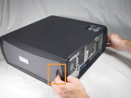
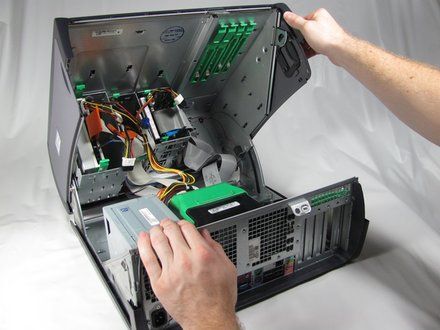
• Lay the Dell Optiplex GX260 down on a clean flat surface with the rear towards you.
• Push the oval shaped buttons located on the top and bottom of the PC simultaneously and lift the case straight up.
• NOTE: Note: Some force may be required to push in the oval buttons open the PC case.
|
|
|
| | | |
| | 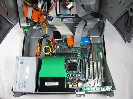
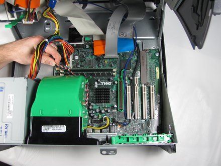
• Disconnect the fan cable from the motherboard.
|
|
|
| | | |
| | 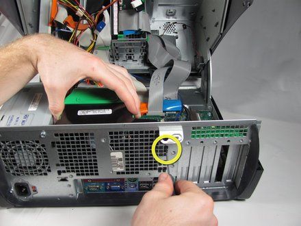
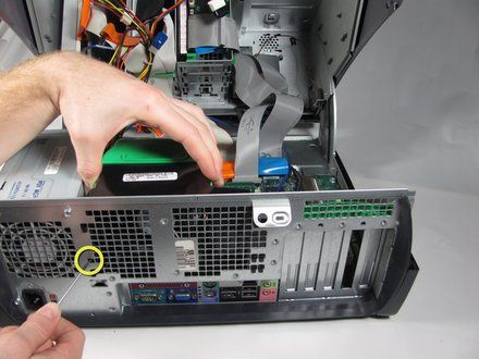
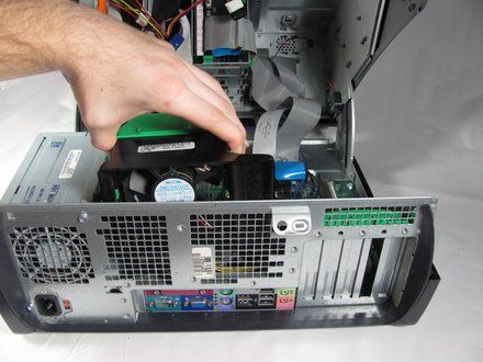
• On the rear of the desktop, push the two circled black buttons straight in with a small pointed object while pulling up on the fan.
• Once the fan is released, lift it straight up and out of the case.
|
|
|
| | | |
| | 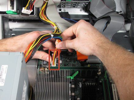
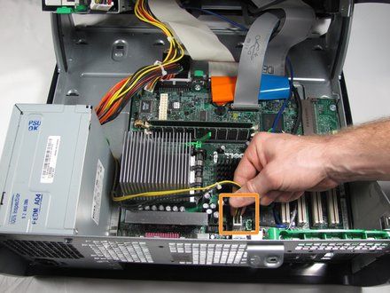
• Disconnect the ATX power cable to the motherboard.
• Disconnect the P4 12V(4x2) power cable from the motherboard.
|
|
|
| | | |
| | 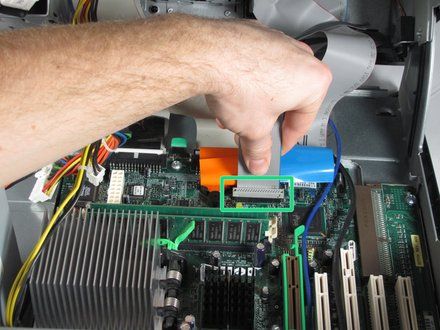
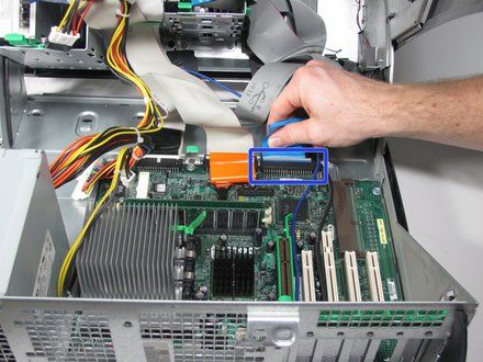
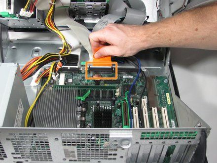
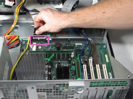
• Disconnect the front panel ribbon cable by gently pulling it straight up.
• Disconnect the hard drive ribbon cable by gently pulling the blue tab away from the motherboard.
• Disconnect the optical drive ribbon cable by gently pulling the orange tab away from the motherboard.
|
|
|
| | | |
| | 
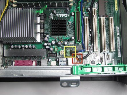
• Disconnect the floppy drive drive ribbon cable by gently pulling the black tab away from the motherboard.
• Disconnect the optical drive audio cable connector from the motherboard.
• Disconnect the audio input/output cable from the motherboard.
|
|
|
| | | |
| | 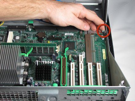
• Lift the metal tab near the right corner of the motherboard.
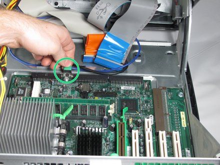
• Pull the green tab toward the front of the PC to release the motherboard.
• From the rear of the PC, push the ports in while lifting the motherboard up and flipping it away from you.
|
|
|
| | | |
| | 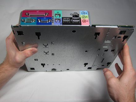
• Stand the motherboard up as shown.
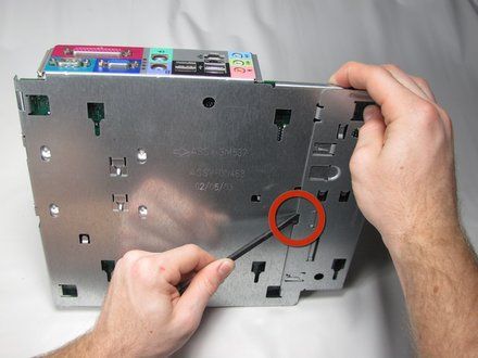
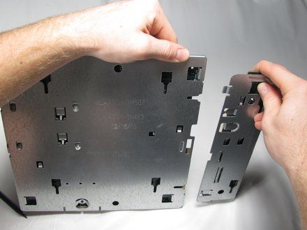
• Insert the flat end of a spudger into the slot in the motherboard mounting plate and press the release tab while pushing the extension plate to the right with your thumbs until it comes off..
|
|
|
| | | |
| | 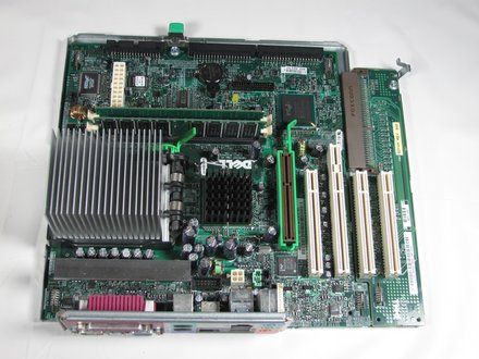
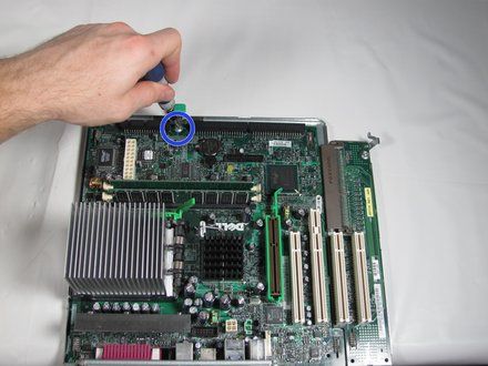
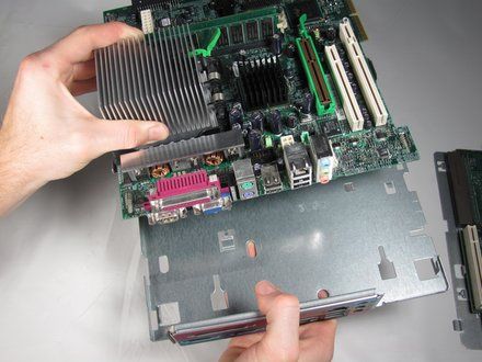
• Remove the screw at the rear of the motherboard.
• Grasp the heat sink with your left hand and the I/O port panel with your right hand and pull to separate motherboard from the metal base.
• NOTE: If you are replacing the motherboard refer to the great iFixit guide for removing the CPU (https://www.ifixit.com/Guide/Dell+OptiPlex+GX260+CPU+Replacement/4002).
|
|
|
| | | |
| | • With the motherboard out of the tray, let your soldering gear warm up and get a desoldering braid.
• NOTE: Since this isn't a Optiplex GX260 motherboard, I have removed the heatsink to get rid of any confusion.
|
|
|
| | | |
| | 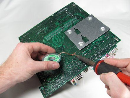
• NOTE: Take note of which way the positive lead marker on the capacitor is facing before removing it. You will need to know for the next step.
• Desoldering can damage motherboards, so first practice on a board you don't need. Use a 40-50W soldering iron with a chisel tip and 0.080" wide desoldering braid. Also helpful are rosin flux and 60/40 tin/lead solder, in case all the solder doesn't come out. Wiggle desoldered leads to verify they're free, and never pull on any that aren't.
|
|
|
| | | |
| | 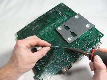
• Install the new capacitor in the holes left by the old one, then solder it into place.
• CAUTION: Caution: Ensure that the new capacitor is inserted with the positive lead mark facing the same direction as the old capacitor. If the direction is switched, the new capacitor will fail.
|
|
|
| | | |
| | | To reassemble your device, follow these instructions in reverse order. |
|
|
| | | |
|


















