|  | | Accounts are free. Join #retro on irc.fxnet.org, identify with NickServ and type !req. |
| |
|
|  | | |
| | #retro on irc.fxnet.org
6697 ssl · 6667 plain
modern + vintage clients welcome |
| |
|
| | | |
| | 3 people in #retro
okawari, synmuffin, thelounge76
nobody on the FTP
last upload: Archived Windows 3.0 - 11 ISO B... by archiveorg, 35d ago |
| as of 21:34 EST ·  |
|
|
| | | |
| | | releases | 2,186 | | last 24h | +0 | | online | 1.7 TB | | library | 1.4 TB | | members | 1 | | updated | 2026-11-18 21:34 |
|
|
|
| | | |
| |
| | 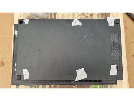
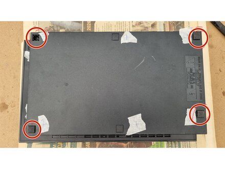
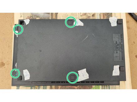
• Flip the PlayStation 2 over so it lays with the bottom of the device facing upwards.
• Use the flat edge of a metal spudger to pry the eight flat screw covers out.
• These covers are made of soft rubber and act as feet.
• These covers are made of hard plastic.
|
|
|
| | | |
| | 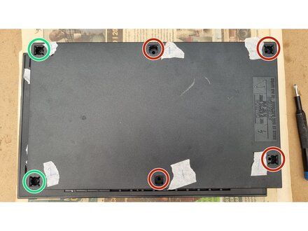
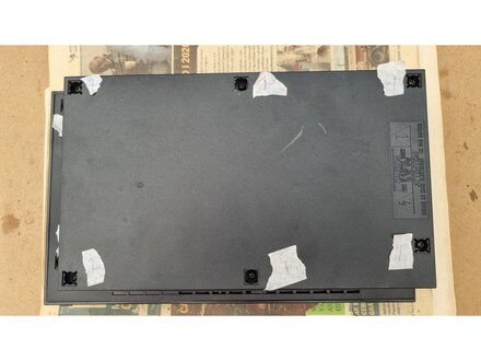
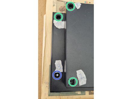
• Use a PH2 screw driver to remove the 8x screws.
• 4x M2.5 x 53 mm black screws.
• 3x M3 x 15 mm black screws.
• 1x M3 x 26.5 mm silver screw.
|
|
|
| | | |
| | 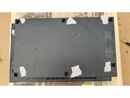
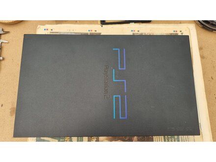
• Flip over the PS2 and make sure the top is face up and the front of the console is nearest to you.
|
|
|
| | | |
| | 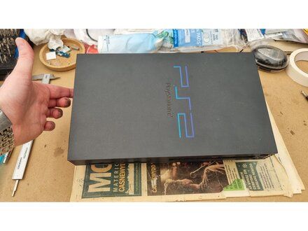
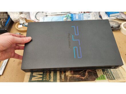
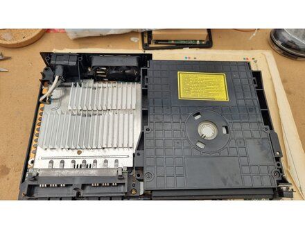
• Lift the rear of the top cover to an angle of about 40-45 degrees.
• Slide the cover forward and over the controller ports, dvd drive and the power/reset and eject buttons.
|
|
|
| | | |
| | 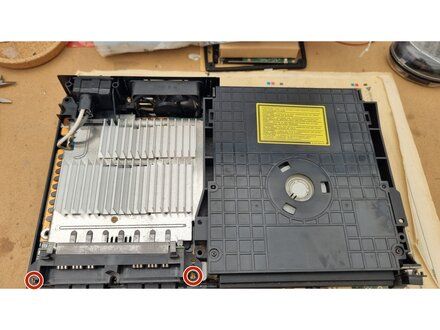
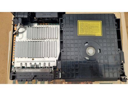
• Use a Phillips PH2 screwdriver to remove the screws holding the controller ports to the base cover.
• 2x M3 x 11.4mm gold coloured screws.
|
|
|
| | | |
| | 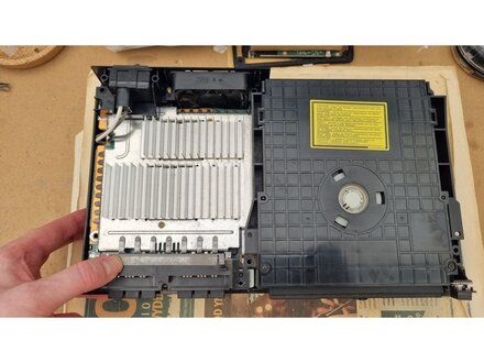
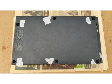
• Flip over the PS2 so the baser cover is facing upwards.
• CAUTION: The controller ports will be loose.
• REMINDER: Hold the the left hand side of controller ports ( and the console) when you flip over the PS2.
|
|
|
| | | |
| | 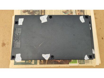
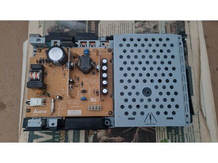
• Lift the base cover straight up to remove it.
|
|
|
| | | |
| | 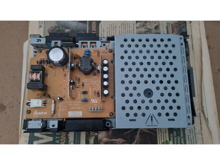
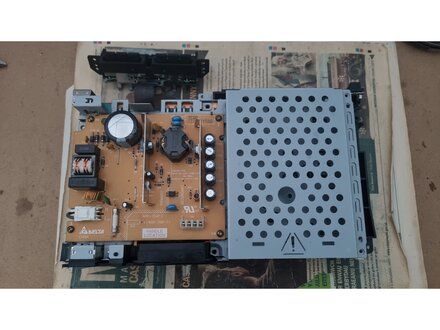
• Move the controller ports away from the console.
|
|
|
| | | |
| | 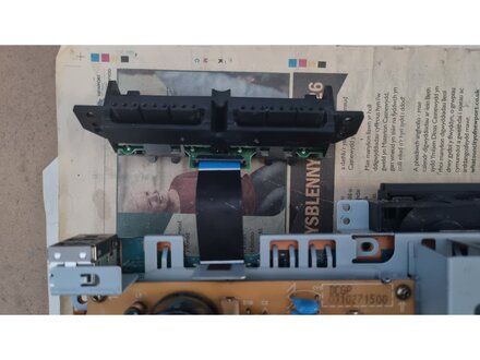
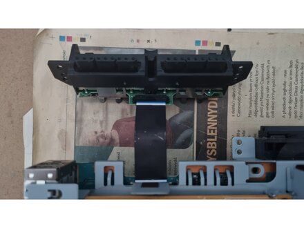
• Unclip the FPC connector on the controller ports pcb.
|
|
|
| | | |
| | 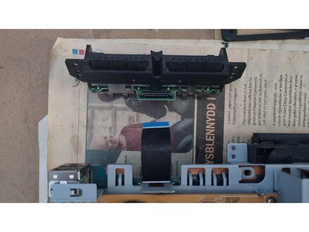
• Remove the flex cable from the controller ports pcb.
|
|
|
| | | |
| | 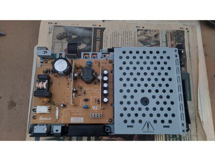
• Controller ports removed.
|
|
|
| | | |
| | 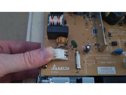
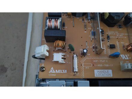
• Press down on the white connector of the AC inlet assembly, then pull the connector towards the left edge of the console.
|
|
|
| | | |
| | 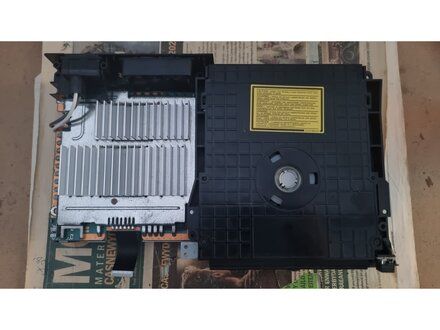
• Flip over the console. The optical drive will be face up and to the right.
|
|
|
| | | |
| | 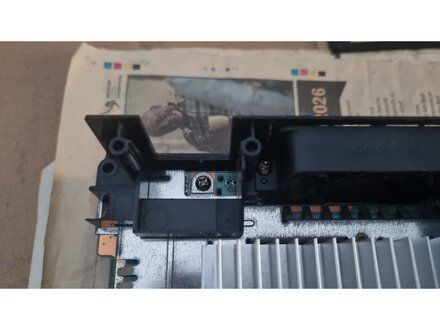
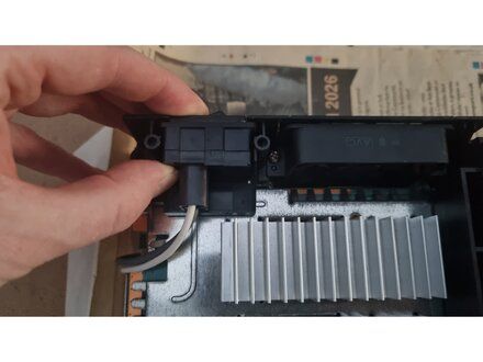
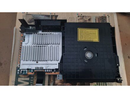
• Slide the AC inlet up and out of the plastic rear bracket.
|
|
|
| | | |
| | 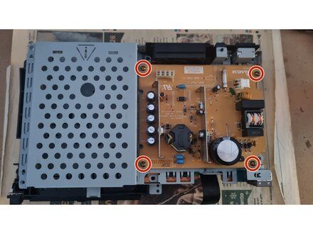
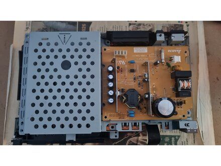
• Use a PH2 screwdriver to remove the 4 screws that secure the power supply to the metal bracket.
• 4x M3 x 6mm gold coloured screws.
|
|
|
| | | |
| | 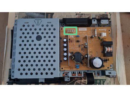
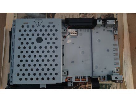
• Lift the power supply board from the metal bracket.
• The power supply is connected to the main board via friction fit connector.
|
|
|
| | | |
| | 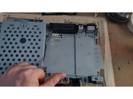
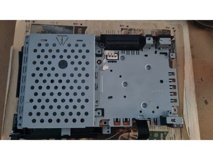
• Remove the plastic insulator sheet.
• NOTE: If you are not proceeding further with disassembly, then there is no need to remove this sheet.
• CAUTION: If you fail to replace this sheet on re-assembly, the power supply board could possibly short out on the metal bracket underneath.
|
|
|
| | | |
| | 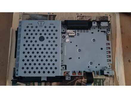
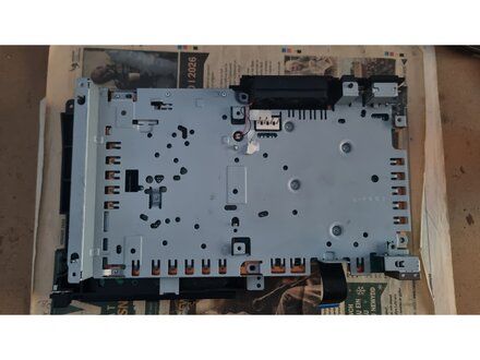
• Lift off the expansion bay.
|
|
|
| | | |
| | 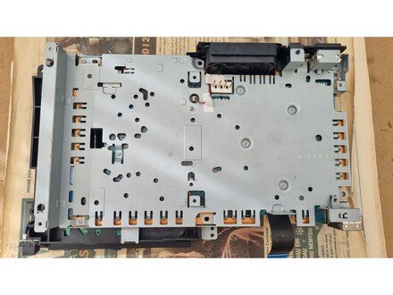
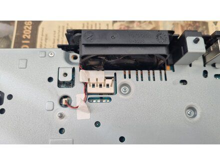
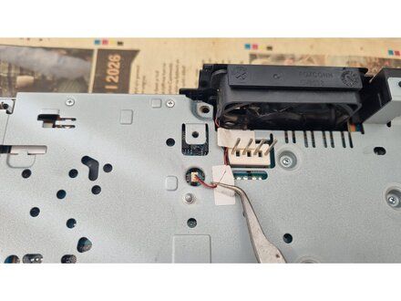
• Peel off the stickers using a pair of pointed tweerzers.
|
|
|
| | | |
| | 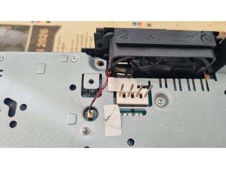
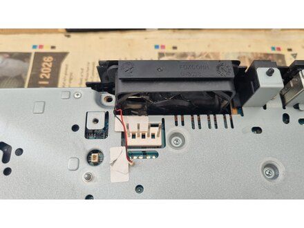
• Use tweezers (preferably blunt ended ones) or fingers to gently disconnect the fan cable from the socket on the motherboard.
|
|
|
| | | |
| | 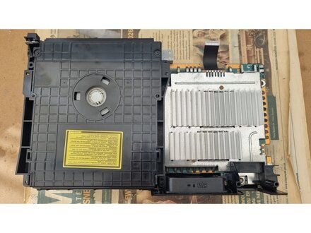
• flip over the console so that the optical drive is on left and the rear fan is facing towards you (and is on the right)
|
|
|
| | | |
| | 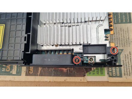
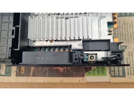
• Use a Phillips #2 screwdriver to remove the two screws.
• One screw is on the right-hand side of the fan and the other is one the right hand side of the rear bracket.
• 2x M3 x 11mm gold screws.
|
|
|
| | | |
| | 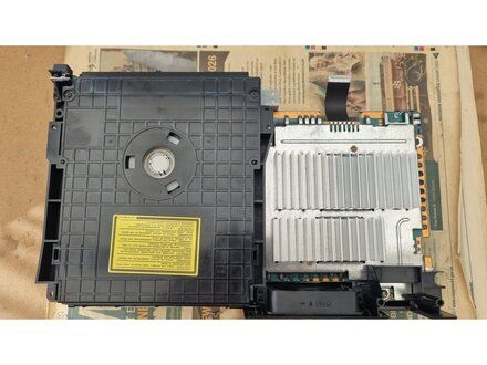
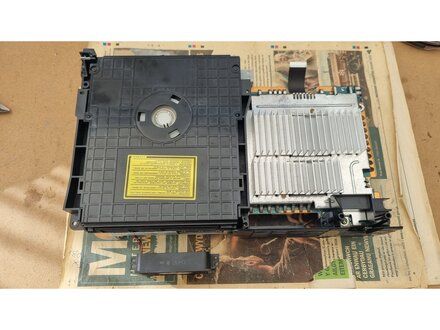
• slide the fan up and out of the rear bracket.
• REMINDER: REASSEMBLY: Remember the orientation of the fan.
• NOTE: There are arrows on the top of the fan to aid correct insertion. one pointing to the rear of the console and one point towards the optical drive.
|
|
|
| | | |
| | 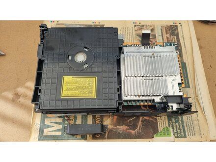
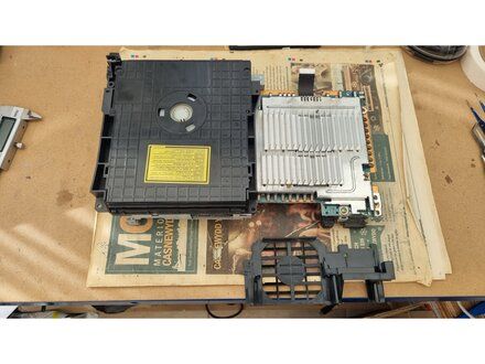
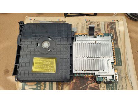
• Remove the rear bracket.
• Lift up the left edge first, then lift off the bracket.
|
|
|
| | | |
| | 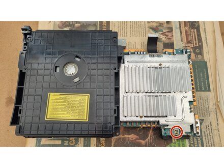
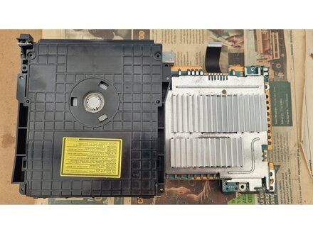
• Use a Phillips #2 screwdriver to remove the single screw underneath the AC inlet.
• 1x M3 x 11mm gold coloured screw.
|
|
|
| | | |
| | 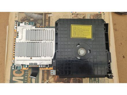
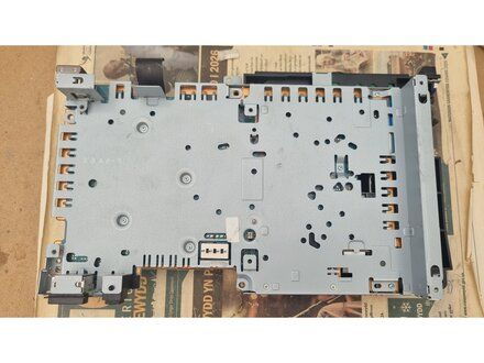
• Flip over the console (motherboard sandwich and optical drive)
|
|
|
| | | |
| | 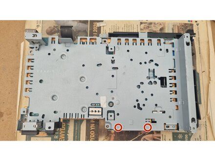
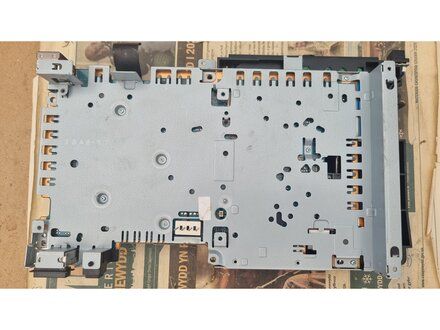
• Using a Phillips #0 screwdriver remove two screws from the upper metal plate.
• 2x M2 x 6.3mm silver screws.
|
|
|
| | | |
| | 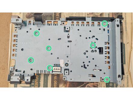
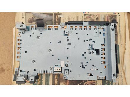
• Using a Phillips #0 screwdriver remove seven screws from the upper metal plate.
• 7x M2 x 5mm silver screws.
|
|
|
| | | |
| | 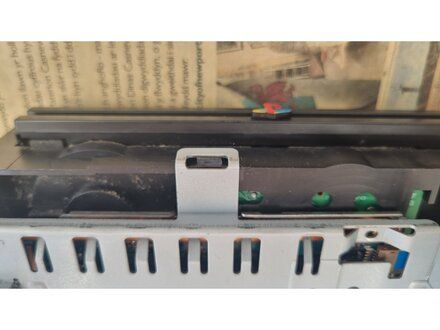
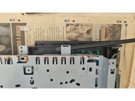
• Loosen clip at the front of the optical drive using a spudger.
• CAUTION: The front of the optical drive is now loose.
|
|
|
| | | |
| | 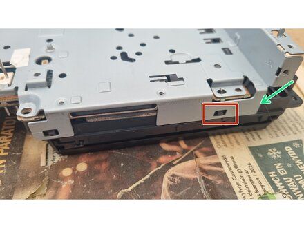
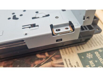
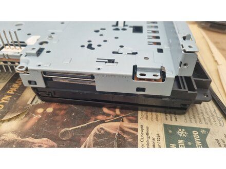
• Loosen the right hand clip on the rear of the optical drive using a spudger.
• When you release the right hand clip, the left hand clip should release on it own (at the same time).
|
|
|
| | | |
| | 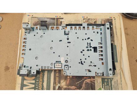
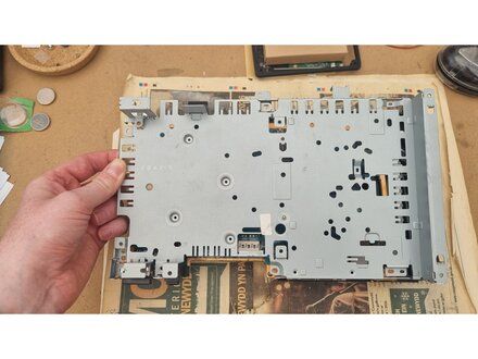
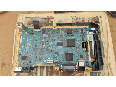
• Gently lift off the lower metal plate.
|
|
|
| | | |
| | 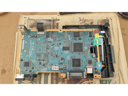
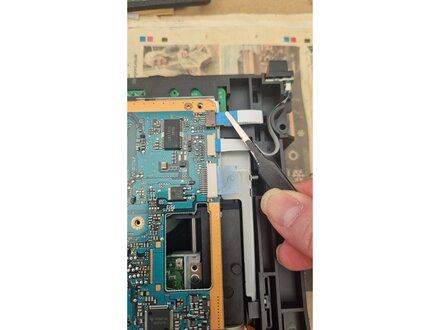
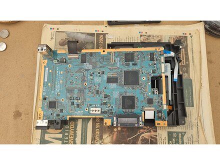
• disconnect the flex cables on the side of the motherboard. There are 4x flex cables on the side of the motherboard that connect to the optical drive,
• Use blunt tweezers or fingers to pull the flex cables from the sockets.
• NOTE: The sockets on the side of the motherboard are friction fit and don't have latches.
• CAUTION: Flex cable are thin and fairly fragile, so handle them with care.
• Disconnect this flex cable first.
• Disconnect this flex cable 2nd.
• Disconnect this flex cable 3rd.
• Disconnect this flex cable 4th and last.
|
|
|
| | | |
| | 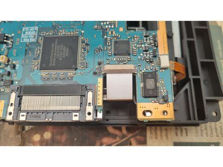
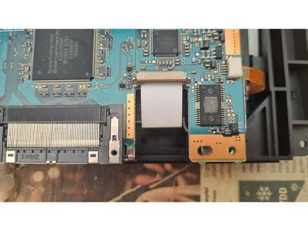
• Use two fingernails (or a spudger) to flip open the FPC connector for the orange flex cable (that connects to the optical drive laser).
|
|
|
| | | |
| | 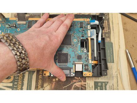
• Hold down the motherboard as shown, as this will make the removal of the laser unit flex cable easier.
|
|
|
| | | |
| | 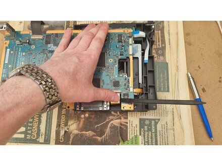
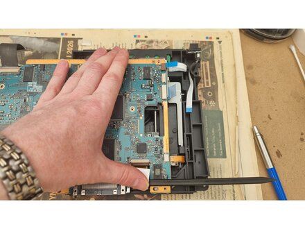
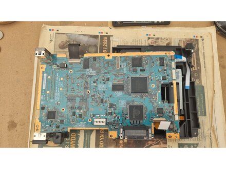
• Use a spudger to gently prise out the laser unit flex cable from the connector on the rear of the motherboard.
|
|
|
| | | |
| | 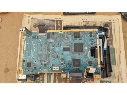
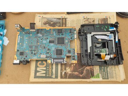
• Gently lift the motherboard and upper metal plate off the optical drive.
• The optical drive should now be fully separate from the rest of the console.
|
|
|
| | | |
| | | To reassemble your device, follow these instructions in reverse order. |
|
|
| | | |
|