|  | | Accounts are free. Join #retro on irc.fxnet.org, identify with NickServ and type !req. |
| |
|
|  | | |
| | #retro on irc.fxnet.org
6697 ssl · 6667 plain
modern + vintage clients welcome |
| |
|
| | | |
| | 3 people in #retro
okawari, synmuffin, thelounge76
nobody on the FTP
last upload: Archived Windows 3.0 - 11 ISO B... by archiveorg, 35d ago |
| as of 21:42 EST ·  |
|
|
| | | |
| | | releases | 2,186 | | last 24h | +0 | | online | 1.7 TB | | library | 1.4 TB | | members | 1 | | updated | 2026-11-18 21:42 |
|
|
|
| | | |
| |
| | 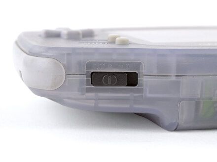
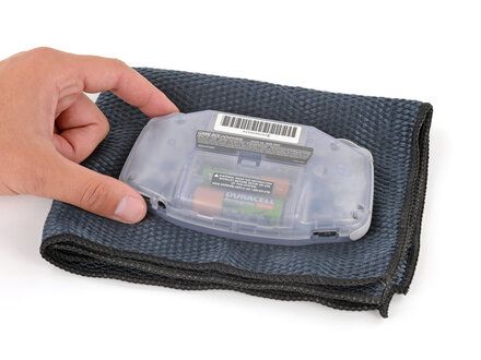
• Before working on your Game Boy, turn the power switch to the OFF position and unplug any cables.
• If you have a game cartridge installed, remove it.
• NOTE: Since your Game Boy will be laying screen?side down for most of your repair, consider placing it on a clean cloth for protection.
|
|
|
| | | |
| | 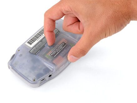
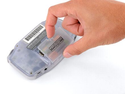
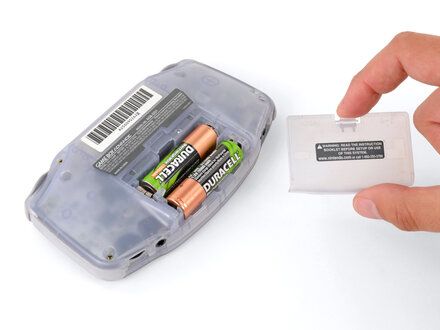
• Release the battery cover tab with your finger and swing the cover away from your Game Boy to remove it.
• REMINDER: During reassembly, insert the tabs on the bottom edge of the cover into their cutouts and press the cover into place.
|
|
|
| | | |
| | 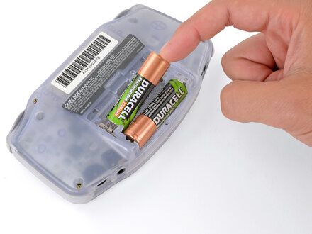
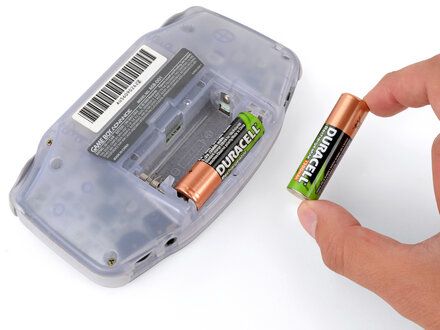
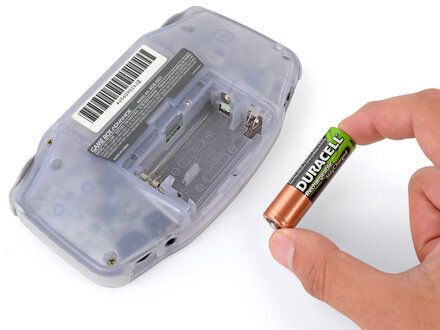
• Remove the two AA batteries.
• NOTE: If the metal terminals are corroded, follow this guide (https://www.ifixit.com/Guide/How+to+Clean+Corroded+Battery+Terminals/164164) to clean them.
• REMINDER: When installing batteries, use the diagram (https://guide-images.cdn.ifixit.com/igi/CuXVhApCfFZ6DpLL.full) in the battery well to properly orient them.
|
|
|
| | | |
| | 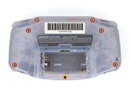
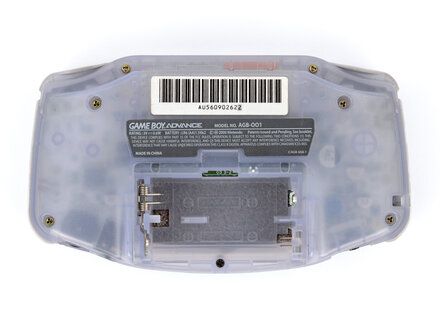
• Remove the seven screws securing the back shell:
• Six 9.4 mm?long tri?point Y0 screws
• One 8.5 mm?long JIS 1 screw
• NOTE: You can try to use a non-iFixit Phillips driver in a pinch, but you risk damaging or stripping screws. Push down firmly on the driver and twist slowly.
|
|
|
| | | |
| | 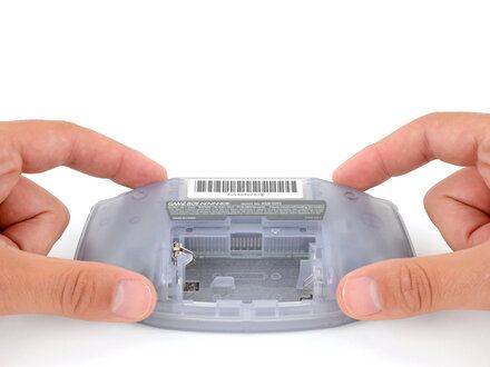
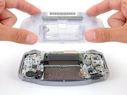
• Lift the back shell straight up and remove it.
• REMINDER: During reassembly, squeeze the shell firmly around the edges and ensure the shoulder buttons and bumpers are properly seated with no large gaps. Gently test the buttons to make sure everything feels correct.
|
|
|
| | | |
| | 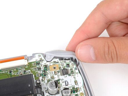
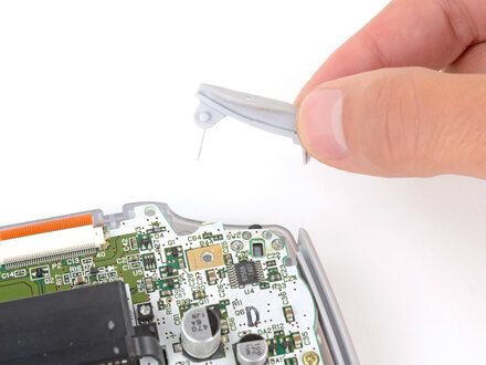
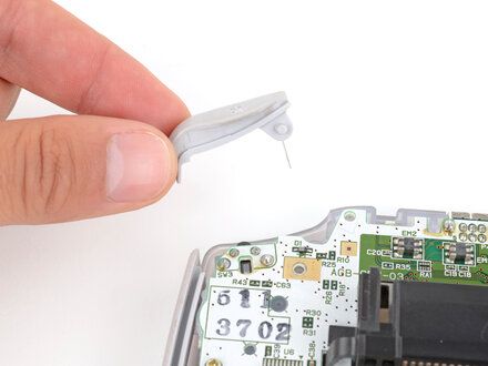
• Lift the shoulder buttons (aka L and R buttons) straight up to remove them.
• REMINDER: During reassembly:
• NOTE: Since your Game Boy is laying upside down, the L button will go on your right?hand side, and the R button will go on your left?hand side.
• Slide the buttons into place, making sure the peg on the button goes into its circular cutout (https://guide-images.cdn.ifixit.com/igi/6uv5K3IvtUbTWpHb.full) and the button itself is over the actual button mechanism (https://guide-images.cdn.ifixit.com/igi/HeFoECHJVlymkoFg.full).
• NOTE: The shoulder buttons will sit on the inside edge of the side bumpers.
• Gently test the buttons to make sure they feel correct. If they don't, reposition them and make sure the metal arms aren't stuck in a weird position under the board.
|
|
|
| | | |
| | 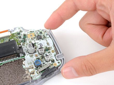
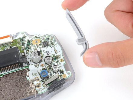
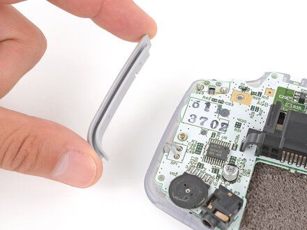
• Remove the side bumpers.
|
|
|
| | | |
| | 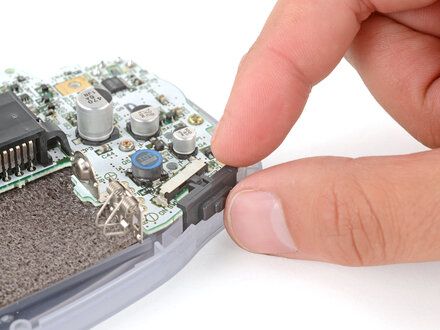
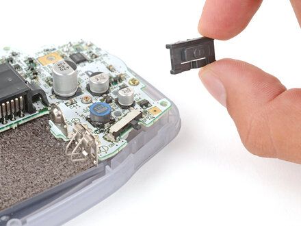
• Remove the power switch cover.
• REMINDER: During reassembly, make sure the switch cover is properly slotted (https://guide-images.cdn.ifixit.com/igi/sXcLGbJnZeJ4ZkJg.full) around the arm on the switch mechanism.
|
|
|
| | | |
| | 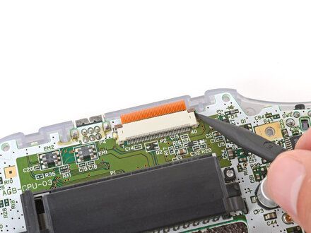
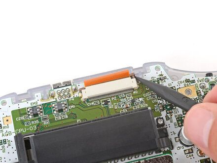
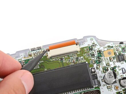
• Use the point of a spudger to fully push up both locking tabs on either side of the screen cable connector.
• NOTE: You should feel the tab click into its unlocked position. Don't push too far, or the tab may slide completely out of the connector.
|
|
|
| | | |
| | 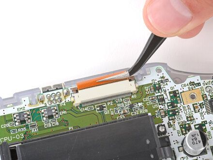
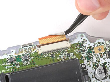
• Use tweezers to slide the cable straight out of its socket.
• NOTE: The cable should come out with little to no force. If you feel resistance, the tab may not be fully unlocked.
|
|
|
| | | |
| | 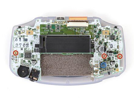
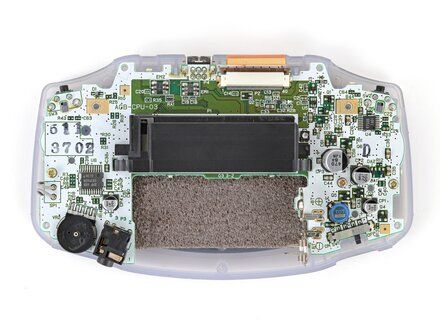
• Use a JIS 1 screwdriver to remove the three 7 mm?long screws securing the motherboard.
|
|
|
| | | |
| | 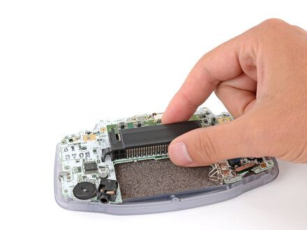
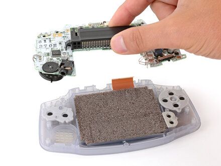
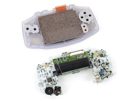
• Use your fingers to grip the cartridge reader and lift the motherboard straight up to remove it.
• REMINDER: During reassembly, make sure the speaker gets correctly slotted into its circular cutout (https://guide-images.cdn.ifixit.com/igi/swBAQPOBrGOWavOw.full) (including a small tab on the bottom (https://guide-images.cdn.ifixit.com/igi/5eExCUBMjC1HeKYn.full)) when lowering the motherboard into place.
|
|
|
| | | |
| | To reassemble your device, follow these instructions in reverse order.
Take your e-waste to an R2 or e-Stewards certified recycler (https://www.ifixit.com/Wiki/E-Waste).
Repair didn't go as planned? Try some basic troubleshooting (https://www.ifixit.com/Wiki/Troubleshooting_Problems_After_a_Repair), or ask our Answers Community (https://www.ifixit.com/Answers/Device/Game_Boy_Advance) for troubleshooting help. |
|
|
| | | |
|































