|  | | Accounts are free. Join #retro on irc.fxnet.org, identify with NickServ and type !req. |
| |
|
|  | | |
| | #retro on irc.fxnet.org
6697 ssl · 6667 plain
modern + vintage clients welcome |
| |
|
| | | |
| | 3 people in #retro
okawari, synmuffin, thelounge76
nobody on the FTP
last upload: Archived Windows 3.0 - 11 ISO B... by archiveorg, 35d ago |
| as of 21:42 EST ·  |
|
|
| | | |
| | | releases | 2,186 | | last 24h | +0 | | online | 1.7 TB | | library | 1.4 TB | | members | 1 | | updated | 2026-11-18 21:42 |
|
|
|
| | | |
| |
| | 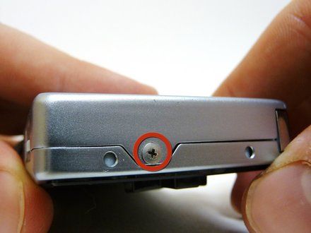
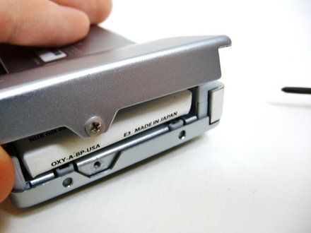
• Remove the Phillips #00 screw on the side of the Game Boy closest to the directional pad.
• Once the screw has been loosened, lift the cover off the back of the device.
|
|
|
| | | |
| | 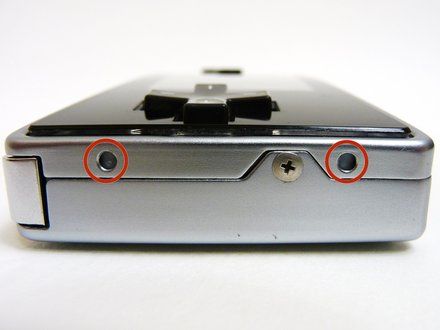
• Locate the two circular holes on the side of the Game Boy nearest to the directional pad.
|
|
|
| | | |
| | 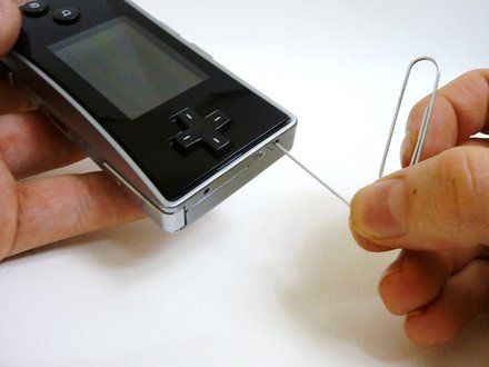
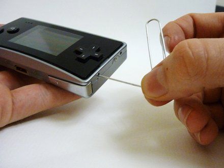
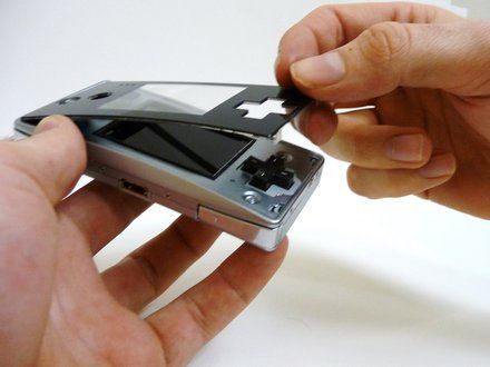
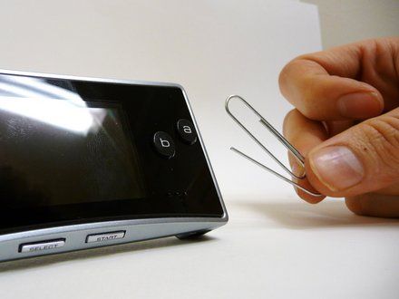
• Straighten the end of a paper clip and push it into each of the circular holes.
• NOTE: You may hear a faint click afterwards.
• Use the paper clip to lever the faceplate off from the unit.
|
|
|
| | | |
| | 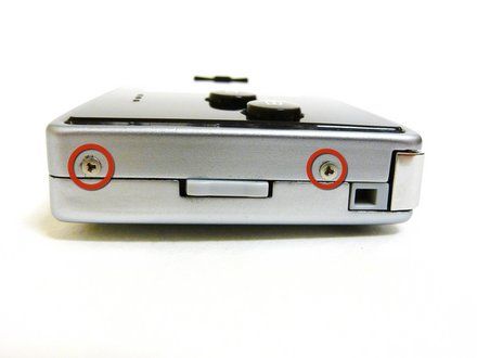
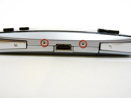
• Remove the two tri-wing screws on the top of the Game Boy and the two screws next to the volume/contrast switch.
|
|
|
| | | |
| | 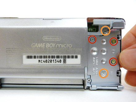
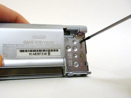
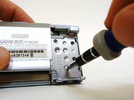
• Remove the three Phillips #00 screws.
• Remove the two tri-wing screws.
|
|
|
| | | |
| | 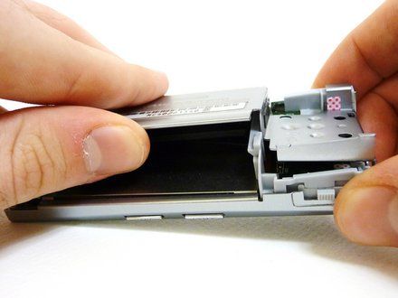
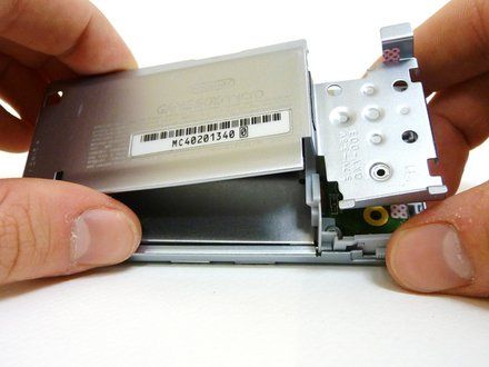
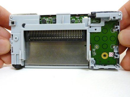
• Lift the back cover off of the Game Boy.
|
|
|
| | | |
| | 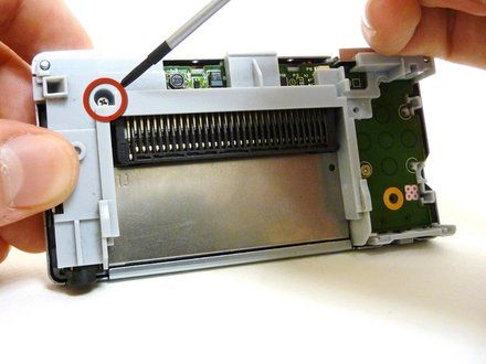
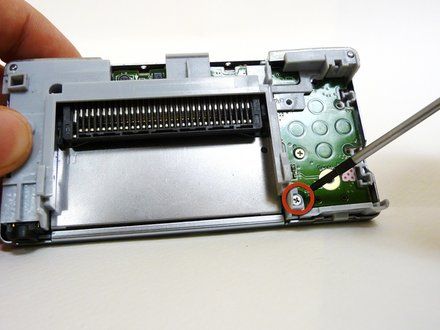
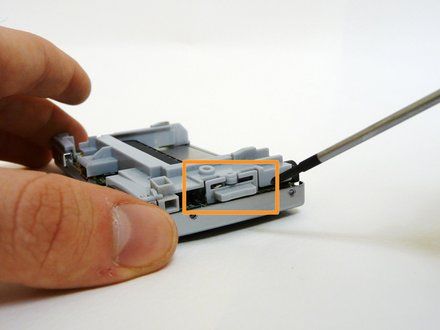
• Remove the two Phillips #00 screws from the plastic frame.
• As you are pulling off the plastic frame, the shoulder buttons and the volume switch may fall out of the device.
• NOTE: Underneath each shoulder button is a small spring. Do not lose them.
|
|
|
| | | |
| | 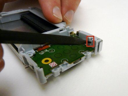
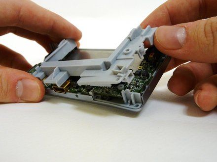
• With a spudger, depress the small clip on the lower right corner of the plastic guard.
• Grab the edges of the plastic frame and lift the frame off the motherboard.
|
|
|
| | | |
| | 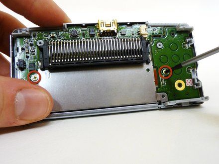
• Remove the two gold Phillips #00 screws from the motherboard.
|
|
|
| | | |
| | 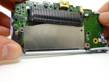
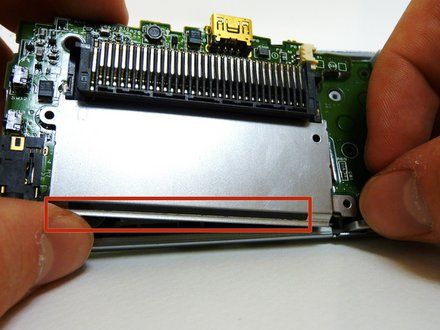
• With one hand, gently slide the top left end of the motherboard up and out of the front case.
• With your other hand, pull out the EMI shield until the tab comes out of the front case.
• Once the tab is pulled out from the bottom, slide the EMI shield down and out of the device.
|
|
|
| | | |
| | 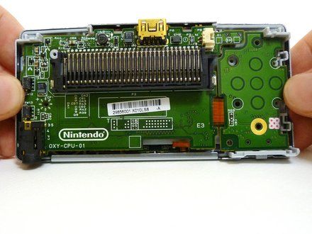
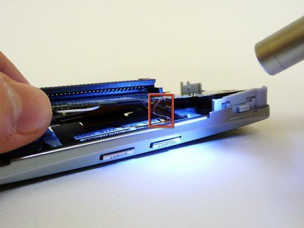
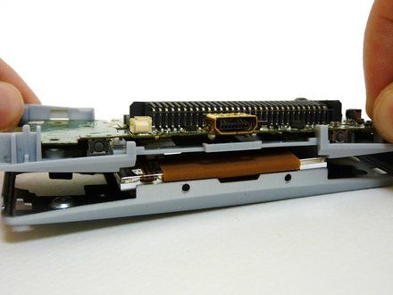
• The entire motherboard is now accessible.
• CAUTION: Take extreme care when working with the motherboard to avoid damaging the device and its components.
• A small ribbon cable connects the start and select buttons to the motherboard. It can rip very easily, so do not pull on it.
• Lift the motherboard and the front plastic cover assembly off of the front case.
• NOTE: Once the front case is removed, the plastic on/off switch will fall out of place.
|
|
|
| | | |
| | 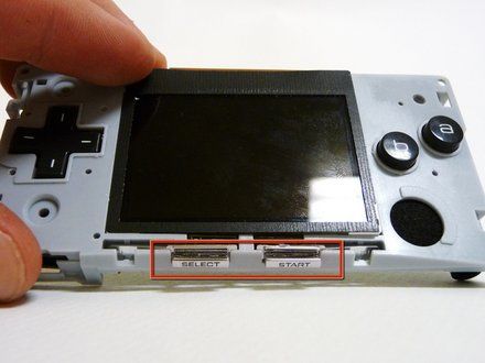
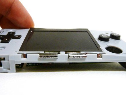
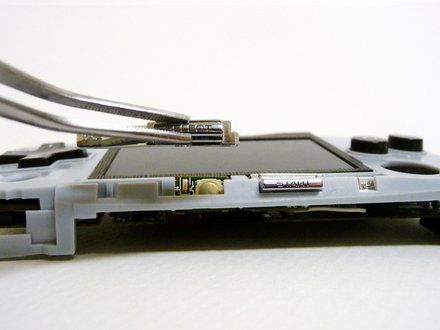
• When you remove the motherboard from the front case, the start and select buttons may fall out.
• If the buttons do not fall out, remove them with a pair of tweezers (https://www.ifixit.com/en-ca/products/tweezers).
|
|
|
| | | |
| | 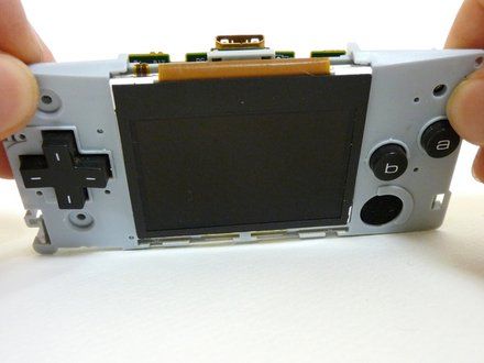
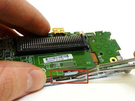
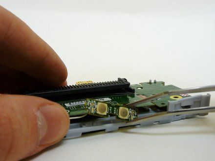
• Without the front case, you will be left with the motherboard and the plastic mount. The LCD screen is attached to the motherboard by a ribbon and can fall off the plastic mount.
• Using metal tweezers, grab the start/select board and slide it out gently.
|
|
|
| | | |
| | 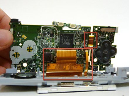
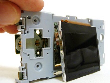
• Lift the entire motherboard assembly off the plastic guard.
• Take caution not to damage any of the gold ribbon cables on the motherboard.
• NOTE: The LCD screen is the only thing connecting the motherboard and plastic guard.
|
|
|
| | | |
| | 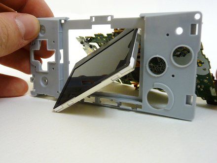
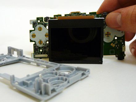
• To remove the LCD screen, carefully angle it until it is diagonal to the square hole in the plastic guard and slide it out.
• It is now possible to remove the entire motherboard assembly from the plastic guard.
|
|
|
| | | |
| | 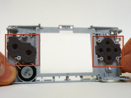
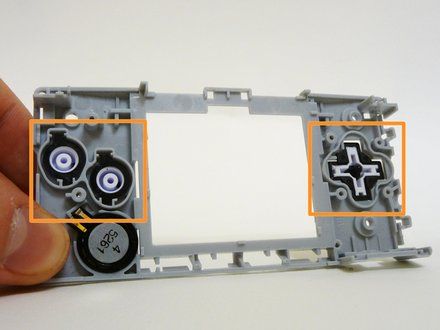
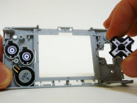
• On the plastic guard, there are two rubber pads that cover the buttons. Remove them.
• NOTE: These pads rest on the motherboard and sometimes stick to it. If they do, peel them off.
• With the rubber pads off, you may use your fingers to remove the buttons to clean or replace them.
• REMINDER: When returning the buttons to the guard, they have to be put back in exactly the way they were pulled out.
|
|
|
| | | |
| | 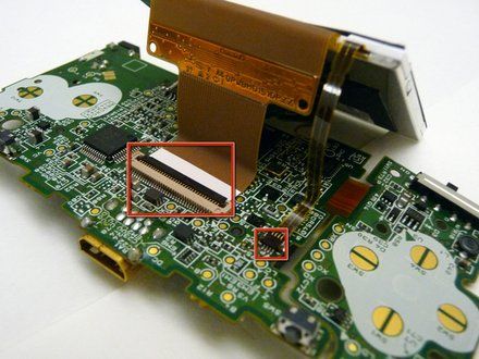
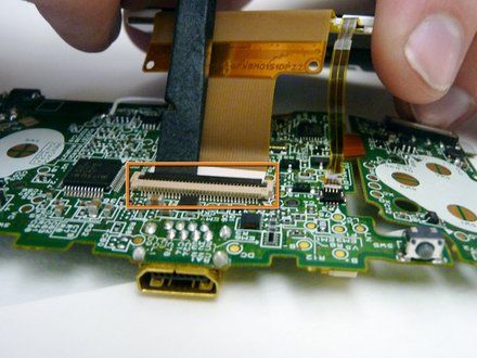
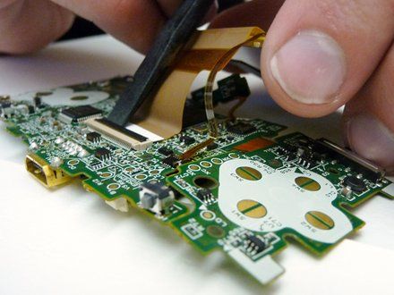
• The LCD screen is connected to the motherboard by two ribbon cables.
• Use a plastic spudger to disconnect the LCD's ZIF connector.
|
|
|
| | | |
| | 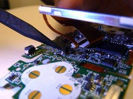
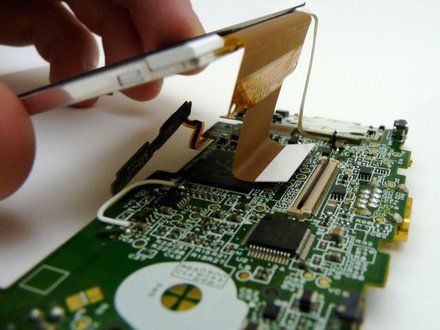
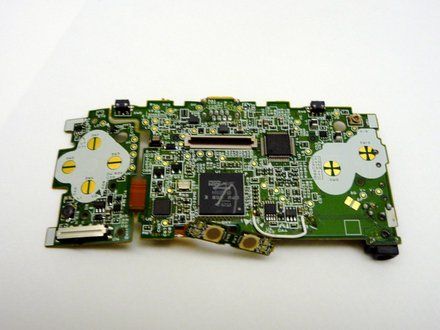
• Use the tip of the spudger to lift the small, black tab holding the thin ribbon.
• With both tabs lifted, pull the ribbons off the motherboard and remove the LCD screen.
|
|
|
| | | |
| | 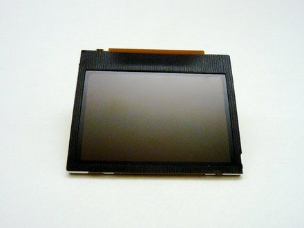
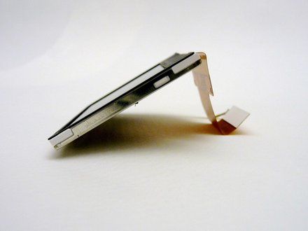
• The LCD can now be cleaned or replaced.
|
|
|
| | | |
| | | To reassemble your device, follow these instructions in reverse order. |
|
|
| | | |
|





















