|  | | Accounts are free. Join #retro on irc.fxnet.org, identify with NickServ and type !req. |
| |
|
|  | | |
| | #retro on irc.fxnet.org
6697 ssl · 6667 plain
modern + vintage clients welcome |
| |
|
| | | |
| | 3 people in #retro
okawari, synmuffin, thelounge76
nobody on the FTP
last upload: Archived Windows 3.0 - 11 ISO B... by archiveorg, 35d ago |
| as of 21:42 EST ·  |
|
|
| | | |
| | | releases | 2,186 | | last 24h | +0 | | online | 1.7 TB | | library | 1.4 TB | | members | 1 | | updated | 2026-11-18 21:42 |
|
|
|
| | | |
| | | |
| Device | Cafetera Nespresso KRUPS XN 304 |
| Difficulty | Moderate |
| Time | 1 hour |
| Steps | 17 |
This guide is by Carlos López (España - Spain) on iFixit and is licensed under Creative Commons Attribution-NonCommercial-ShareAlike 3.0. ByteRot mirrors it for non-commercial preservation: formatting changed and photos resized for old browsers; full-size photos and the text are on the FTP in /DOCS/REPAIR. Original guide >> |
|
|
| | | |
| | 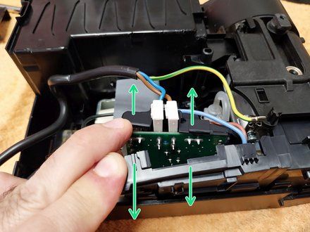
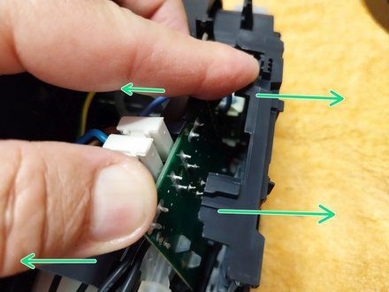
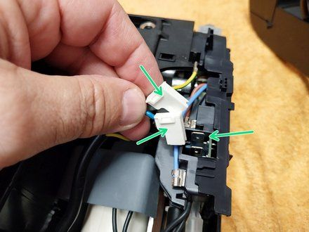
• You can find the previous Teardown step here: (https://www.ifixit.com/Topic/Cafetera_Nespresso_KRUPS_XN_304) In this case, without completely disassembling the machine, I was able to access and extract the circuit board, although with a slight difficulty, by opening the two casings to the sides.
• This same repair and procedure also applies to the KRUPS XN100* coffee maker (https://www.ifixit.com/Topic/Cafetera_Nespresso_KRUPS_XN_100110) and other similar ones.
• First, disconnect the two white power input spade connectors.
|
|
|
| | | |
| | 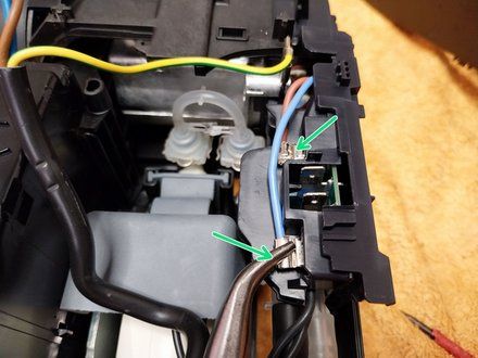
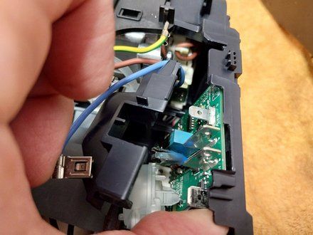
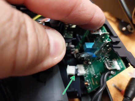
• Disconnect the 2 boiler power faston connectors second.
• Third, release the lower white connector.
|
|
|
| | | |
| | 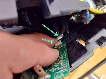
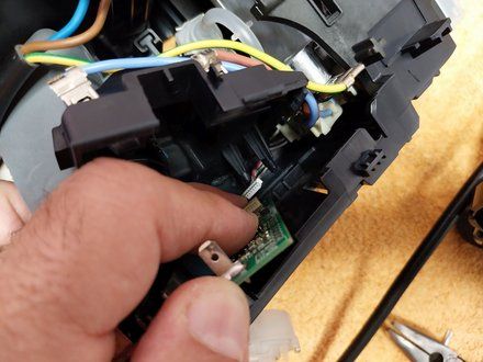
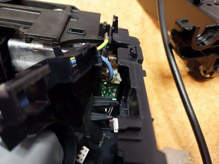
• 4th This one is the most complicated to access; we will release the connector corresponding to the button board.
• With all the connectors released, we can extract the electronic PCB.
|
|
|
| | | |
| | 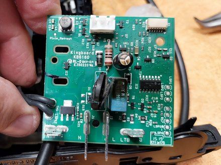
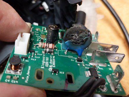
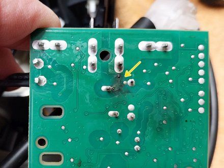
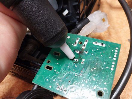
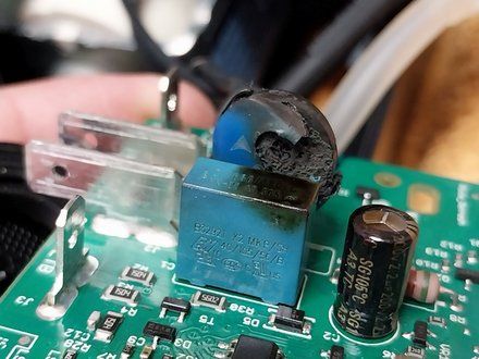
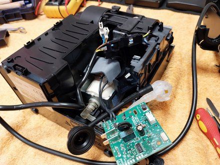
• Here we can already see the "damage" caused by the varistor explosion.
• Blown Varistor.
• It has scorched and darkened the nearby capacitor, although it has not actually affected it.
• And with the copper trace between the power input and the varistor pin burned, the trace has acted as a fuse.
|
|
|
| | | |
| | 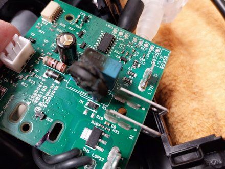
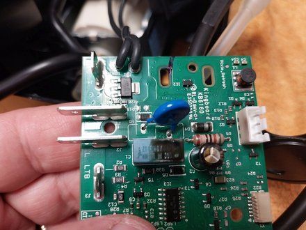
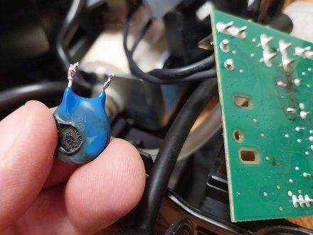
• View of the varistor and the blue capacitor; despite the blackened appearance, the capacitor is usually still OK.
|
|
|
| | | |
| | 
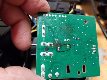
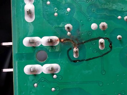
• For the repair, the varistor is replaced. As it is a machine that operates in Spain on a 230 V power grid, I am replacing the varistor with a 275 V one; the burnt fuse-function trace must also be repaired.
• Personally, I find it very useful to mark the components with a permanent marker on the side of the traces and solder joints to work more comfortably.
|
|
|
| | | |
| | 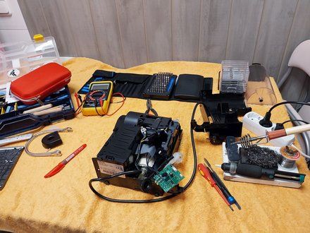
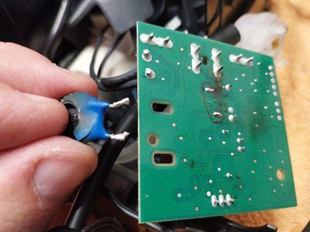
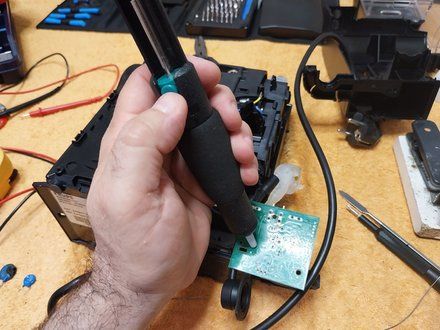
• Desoldering the burnt varistor and soldering the replacement.
|
|
|
| | | |
| | 
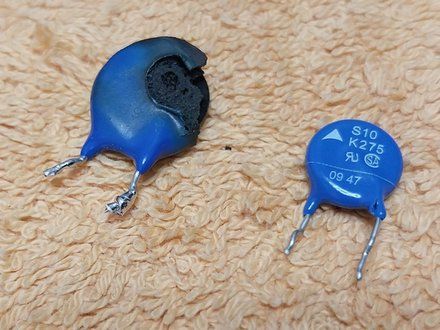
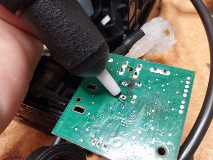
• Cleaning the solder holes using a soldering iron and a desoldering pump.
|
|
|
| | | |
| | 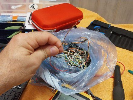
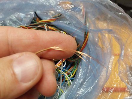
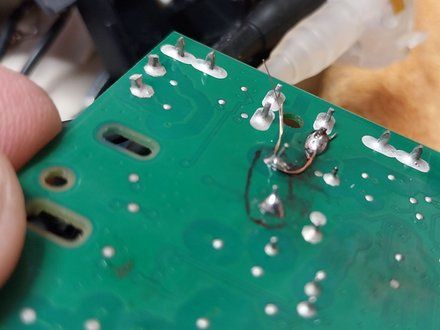
• The blown trace can be repaired using two separate strands from a thin wire; look for a piece in the "cable bag."
• Soldering two wire strands, pending trimming of the excess.
|
|
|
| | | |
| | 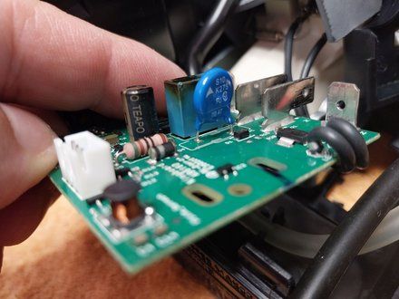
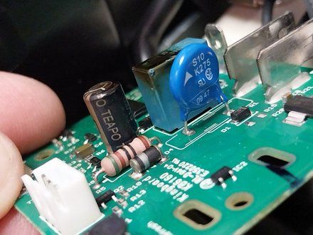
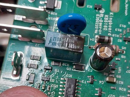
• Views of the already repaired PCB.
|
|
|
| | | |
| | 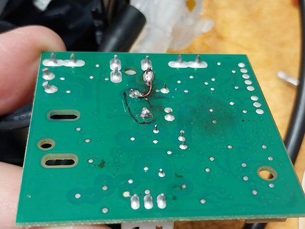
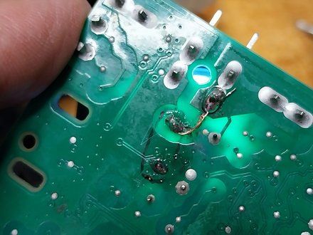
• Detail of the burnt trace repair, with the excess wire already trimmed.
|
|
|
| | | |
| | 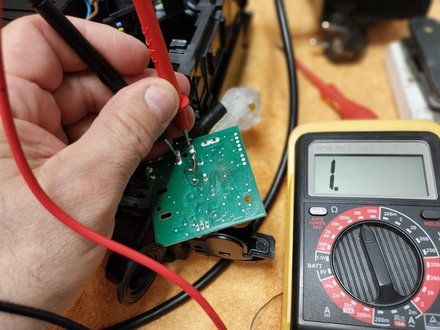
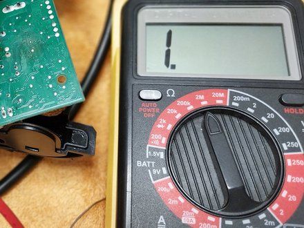
• Check with a multimeter on the ohms scale that, once the copper trace has been repaired, there is no short circuit at the power input.
|
|
|
| | | |
| | 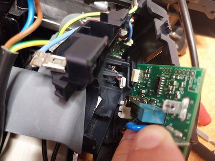
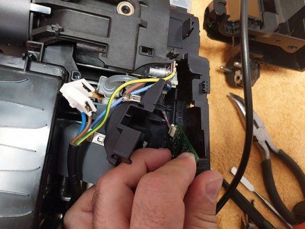
• Insert the board into the machine and connect its corresponding connectors.
|
|
|
| | | |
| | 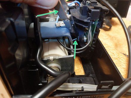
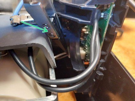
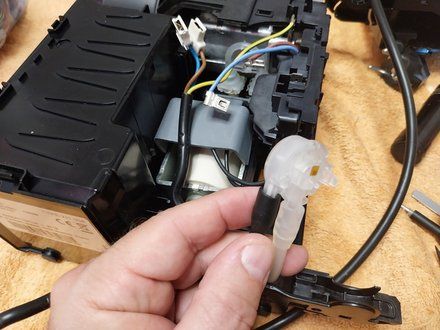
• For the 2 most hidden connectors, we can use tweezers to assist.
• With the 2 bottom connectors connected, we will hook the mass airflow sensor to the board.
|
|
|
| | | |
| | 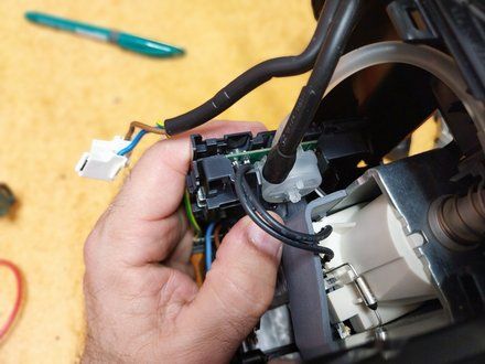
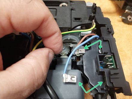
• Photo 1: Flow meter installed. Photo 2: the 2 faston connectors of the boiler are inserted.
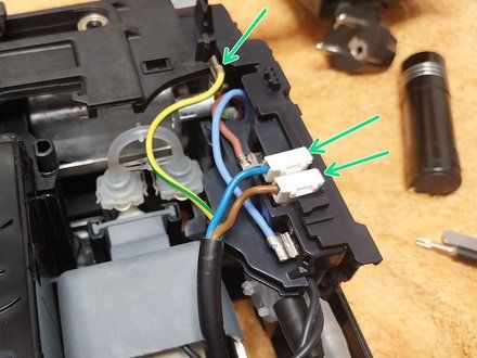
• And finally, we insert the 2 power input Faston connectors + the ground faston.
|
|
|
| | | |
| | 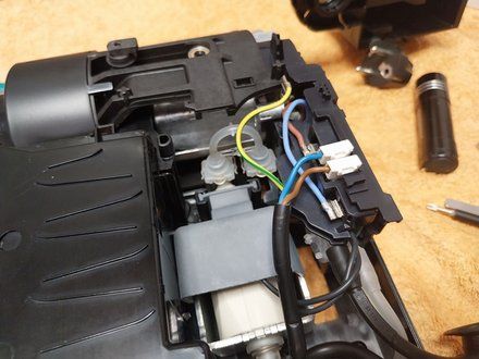
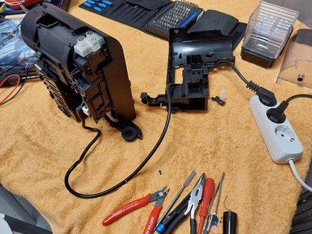
• Once the circuit board is reassembled, before mounting the rest of the machine, plug it into the wall outlet and verify that the two cup buttons light up green.
• Repaired PCB.
• END of Guide 2.
• Other guides in this series: Cafetera Nespresso KRUPS XN 304 (https://www.ifixit.com/Topic/Cafetera_Nespresso_KRUPS_XN_304)
|
|
|
| | | |
| | | To reassemble your device, follow these instructions in reverse order. |
|
|
| | | |
|