|  | | Accounts are free. Join #retro on irc.fxnet.org, identify with NickServ and type !req. |
| |
|
|  | | |
| | #retro on irc.fxnet.org
6697 ssl · 6667 plain
modern + vintage clients welcome |
| |
|
| | | |
| | 3 people in #retro
okawari, synmuffin, thelounge76
nobody on the FTP
last upload: Archived Windows 3.0 - 11 ISO B... by archiveorg, 35d ago |
| as of 21:42 EST ·  |
|
|
| | | |
| | | releases | 2,186 | | last 24h | +0 | | online | 1.7 TB | | library | 1.4 TB | | members | 1 | | updated | 2026-11-18 21:42 |
|
|
|
| | | |
| |
| | 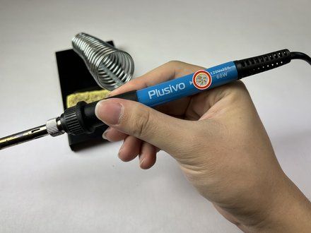
• Set the soldering iron to 300 °C (575 °F) and wait for the iron to heat up to the desired temperature.
• NOTE: Depending on specifications of the soldering iron, it should take between 25-80 seconds for soldering iron to reach desired temperature.
• CAUTION: The soldering iron tip will be very hot! Be careful when handling the soldering iron during operation.
• NOTE: Different solder may have different melting points. Refer to any documentation provided with your solder to determine the recommended temperature.
• CAUTION: Avoid setting the soldering iron to very high temperatures and stay within your solder's specifications. Prolonged exposure to high temperatures can lead to component or board damage.
|
|
|
| | | |
| | 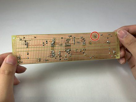
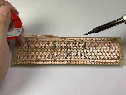
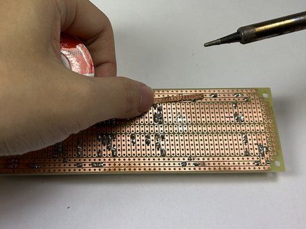
• Locate the solder bridge on the circuit board.
• NOTE: A solder bridge typically bridges two separate contact points (rails).
• NOTE: A multimeter can be used here to check for continuity (a short).
• Apply the solder wick to the affected area.
|
|
|
| | | |
| | 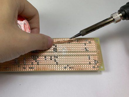
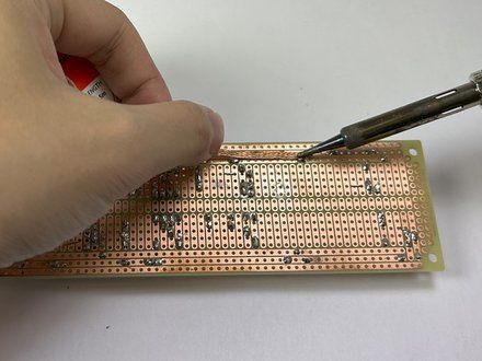
• With the solder wick on top of the solder bridge, heat the wick using the soldering iron by pressing on top of the affected area.
• CAUTION: The solder wick will be very hot! Avoiding touching the area of the wick near the soldering iron.
• NOTE: Alternatively, use wire cutters to cut off about 2 cm (0.75") of braid. Use tweezers (https://www.ifixit.com/en-ca/products/tweezers) or needle nose pliers to place it as described above.
• Continue to apply pressure with the soldering iron to the solder bridge until the solder is melted and absorbed by the wick.
• NOTE: A soldering flux can also be used here to aid in the desoldering process by reducing oxide films.
|
|
|
| | | |
| | 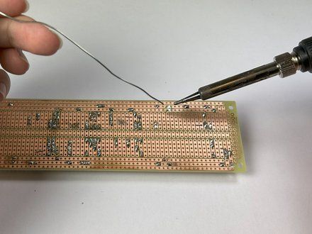
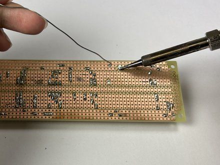
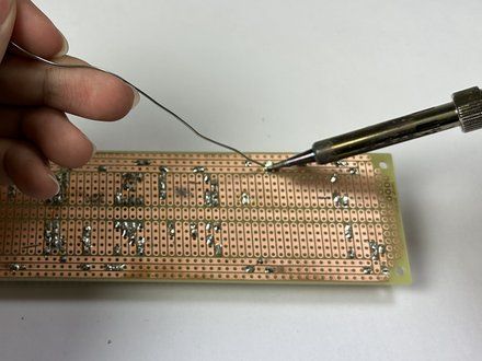
• Apply the soldering iron to the contact point.
• Once the contact point is hot, reapply the solder to the contact point.
• CAUTION: The repaired area will be very hot! Avoid touching the area being repaired.
• Continue applying the solder to the contact point until the pin is solidly attached and the rails are separate from each other.
• NOTE: Step 7 verifies circuit continuity.
|
|
|
| | | |
| | 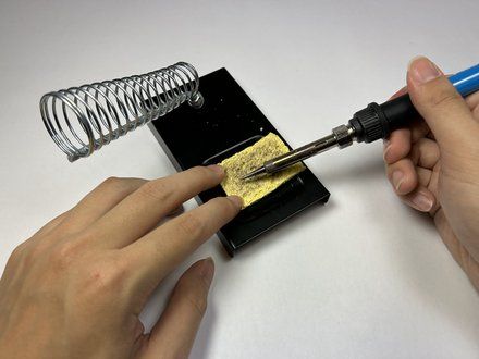
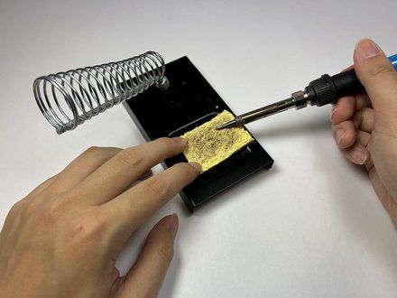
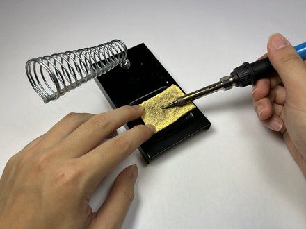
• CAUTION: The soldering iron tip will be very hot! Be careful when handling the soldering iron during its operation.
• Hold down the damp sponge.
• NOTE: Use a damp sponge not a wet sponge so it won't burn. Also make sure the sponge is made from a cellulose material not a polymer. You don't want the sponge to melt and mess up your iron.
• While the soldering iron is hot, use a rubbing motion across the sponge to remove excess solder off the soldering iron tip.
• When you have cleaned the iron, melt a small amount of solder on it to "re-tin" the tip.
|
|
|
| | | |
| | 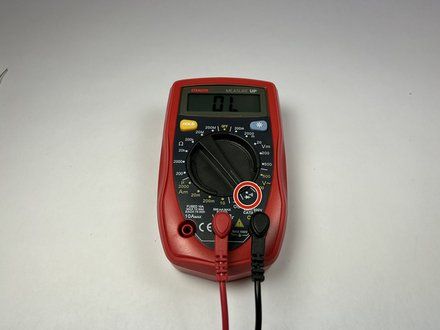
• Connect the red (positive) probe to the Voltage and Resistance Socket.
• Connect the black (negative) probe to the Common/Ground Socket.
• Set the multimeter knob for continuity testing. This is typically labeled with diode/audio symbols.
• NOTE: As shown in the photo, the multimeter will read "OL" if the steps above have been followed properly.
• NOTE: To ensure the functionality of the multimeter, touch the two probes together and an audible beeping sound should be emitted.
|
|
|
| | | |
| | 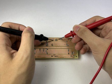
• CAUTION: Verify the circuit board does not have any current supplied to it prior to performing the next steps. If a current is present, permanent damage to the multimeter is possible!
• Connect the black probe to the circuit board rail where one end of the solder bridge was.
• Connect the red probe to the circuit board rail where the other end of the solder bridge was.
• If the fix is successful, the multimeter should read "OL" on the screen, indicating an open circuit. There should be no beep, which means the rails are no longer connected.
• NOTE: If the fix was unsuccessful, the multimeter will give a numerical readout on the multimeter screen, and beep.
|
|
|
| | | |
| | | To reassemble your device, follow these instructions in reverse order. |
|
|
| | | |
|
























