|  | | Accounts are free. Join #retro on irc.fxnet.org, identify with NickServ and type !req. |
| |
|
|  | | |
| | #retro on irc.fxnet.org
6697 ssl · 6667 plain
modern + vintage clients welcome |
| |
|
| | | |
| | 3 people in #retro
okawari, synmuffin, thelounge76
nobody on the FTP
last upload: Archived Windows 3.0 - 11 ISO B... by archiveorg, 35d ago |
| as of 21:42 EST ·  |
|
|
| | | |
| | | releases | 2,186 | | last 24h | +0 | | online | 1.7 TB | | library | 1.4 TB | | members | 1 | | updated | 2026-11-18 21:42 |
|
|
|
| | | |
| |
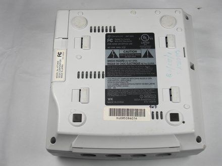
| | 
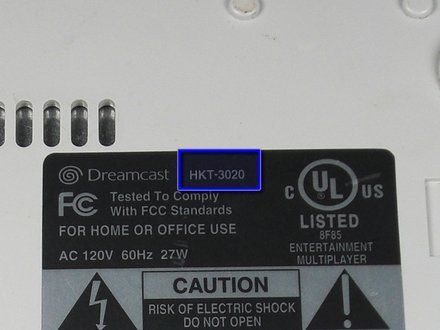
• CAUTION: Verify that the console is disconnected from the AC outlet before you begin.
• Flip the console over on its back.
• Take note of your model number, in case replacement parts are needed.
|
|
|
| | | |
| | 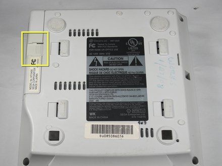
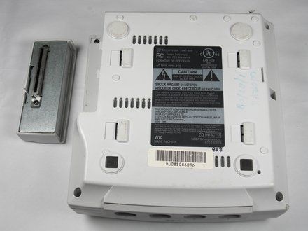
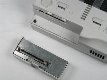
• Remove the expansion bay by applying pressure to the small clip on the expansion bay while prying it away from the console.
|
|
|
| | | |
| | 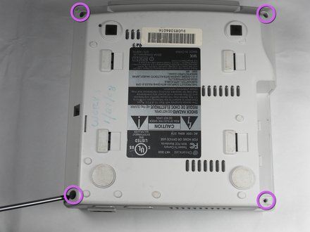
• Locate and remove all four black 12mm Phillips #02 screws from the underside of the console.
• NOTE: Note: Remove the expansion bay to locate the fourth screw
|
|
|
| | | |
| | 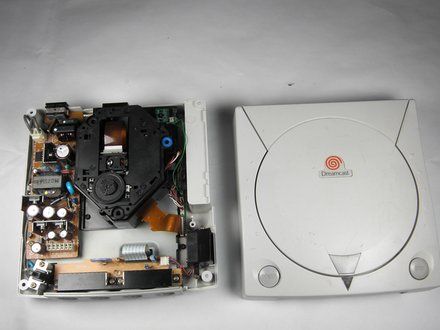
• CAUTION: Internal components can be loose. Be careful that they do not fall out when removing the cover.
• Turn the console right side up.
• Remove the top cover by gently lifting the upper portion of the console.
|
|
|
| | | |
| | 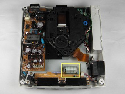
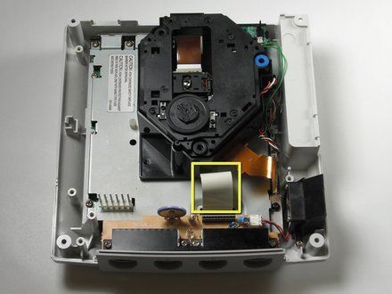
• CAUTION: Be gentle with the white controller cable as it can be a bit fragile.
• Disconnect the white controller cable by gently pulling the the cable while wiggling it back and forth until it detaches from the controller board.
|
|
|
| | | |
| | 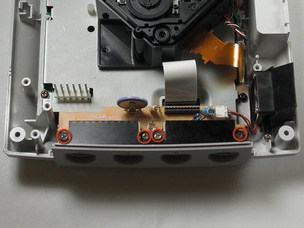
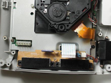
• Remove the four 14mm Philips #02 screws located on the controller board.
|
|
|
| | | |
| | 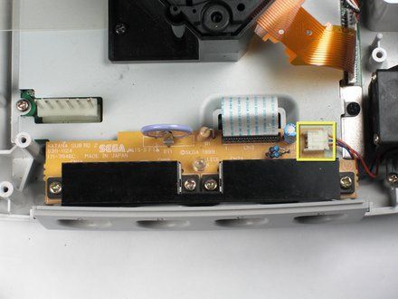
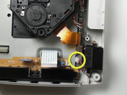
• Disconnect the white fan header from the controller port.
|
|
|
| | | |
| | 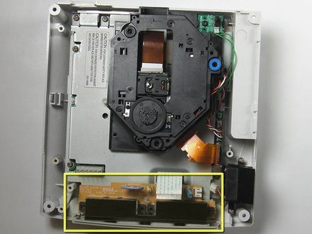
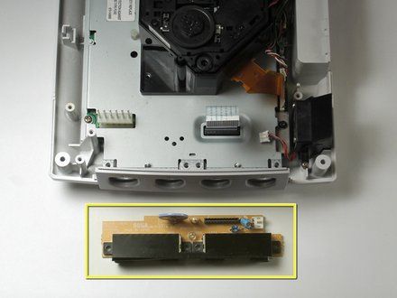
• Remove the controller board by lifting it up from the controller port.
|
|
|
| | | |
| | 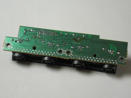
• Flip the controller board on its underside so that the solder joints are exposed.
|
|
|
| | | |
| | 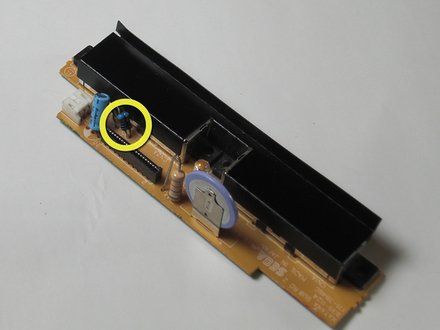
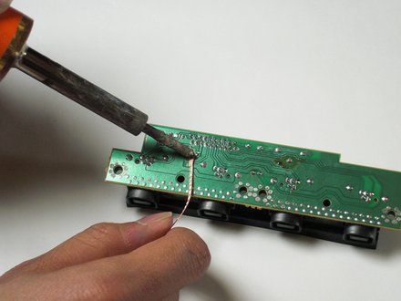
• Remove the F1 fuse by using the soldering iron and desoldering wick.
• The F1 fuse is clearly indicated on the topside of the controller board.
• NOTE: If the F1 through-hole of the circuit board is not visible, you may clean the it by removing the excess solder by using the soldering iron and desoldering wick.
|
|
|
| | | |
| | 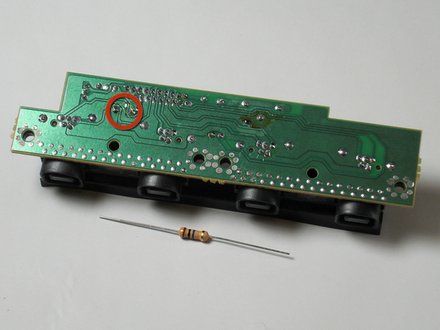
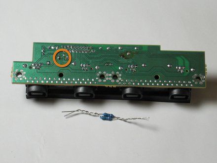
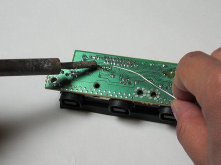
• NOTE: If you are not using a fuse resistor, skip this step. Otherwise, continue.
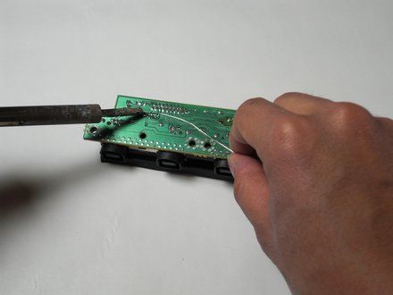
• Insert and solder the new fuse resistor to F1 socket.
• NOTE: The fuse resistor should sit on the topside of the board and the leads should be exposed on the underside. Orientation of the fuse resistor does not matter
• NOTE: The 10M 1/2 watt resistor in the picture is used to depict what a fuse resistor might look like.
|
|
|
| | | |
| | 
• NOTE: If you have already used a fuse resistor to complete the previous step, you may omit this step.
• Insert and solder the parallel (http://en.wikipedia.org/wiki/Series_and_parallel_circuits) 10 ohm 1/4 watt resistors to the F1 socket.
• NOTE: The resistors should be laid out on the top side of the circuit board and the leads should poke out from the underside. The orientation of the resistor does not matter.
• NOTE: The 1/4 watt resistors shown in the picture are used to depict what parallel resistors should look like.
|
|
|
| | | |
| | 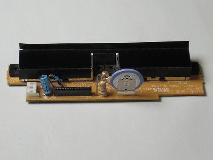
• CAUTION: Verify that the resistor(s) leads do not touch other components on the topside of the circuit board. Otherwise, a short circuit (http://en.wikipedia.org/wiki/Short_circuit) may occur when you power on the system.
|
|
|
| | | |
| | | To reassemble your device, follow these instructions in reverse order. |
|
|
| | | |
|


















