|  | | Accounts are free. Join #retro on irc.fxnet.org, identify with NickServ and type !req. |
| |
|
|  | | |
| | #retro on irc.fxnet.org
6697 ssl · 6667 plain
modern + vintage clients welcome |
| |
|
| | | |
| | 3 people in #retro
okawari, synmuffin, thelounge76
nobody on the FTP
last upload: Archived Windows 3.0 - 11 ISO B... by archiveorg, 35d ago |
| as of 21:42 EST ·  |
|
|
| | | |
| | | releases | 2,186 | | last 24h | +0 | | online | 1.7 TB | | library | 1.4 TB | | members | 1 | | updated | 2026-11-18 21:42 |
|
|
|
| | | |
| |
| | 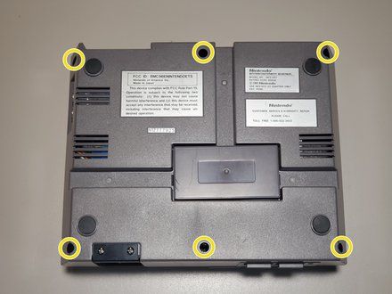
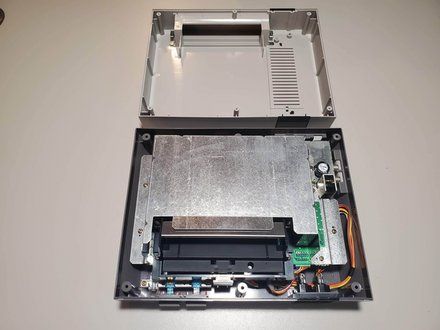
• Remove six 13.25mm Phillips screws on the bottom of the system.
• NOTE: The screws are recessed about 40mm.
• Once all screws are removed, simply lift the bottom half away from the top housing.
|
|
|
| | | |
| | 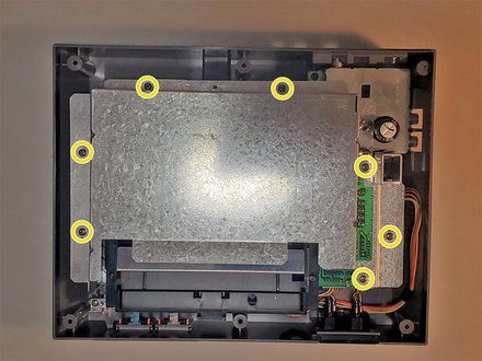
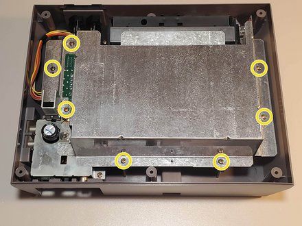
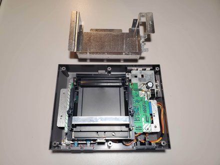
• Remove seven 13.25mm Phillips screws around the perimeter of the RF shield.
• Lift the RF shield up and away from the system and place aside.
|
|
|
| | | |
| | 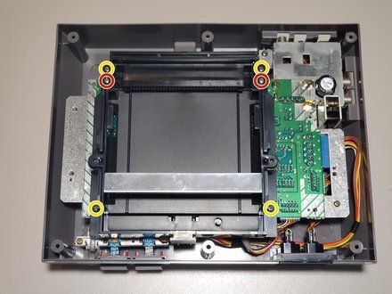
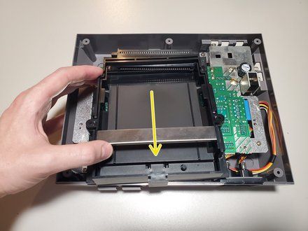
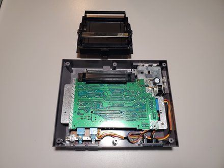
• Remove four 13.25mm Phillips screws from the four corners of the cartridge tray.
• NOTE: Your system may only have two screws on the bottom.
• Remove two 17.25mm Phillips screws from the top of cartridge tray.
• Once free, slide the cartridge tray towards you and then lift slightly in the front to remove.
|
|
|
| | | |
| | 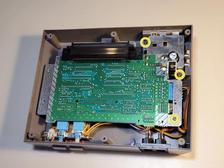
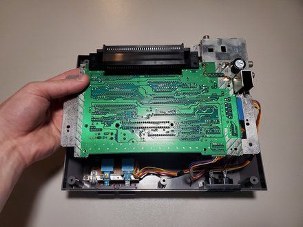
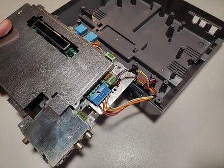
• Remove three 13.25mm Phillips screws to free the motherboard from the bottom housing.
• Carefully lift the motherboard and turn it over to find the wired connections.
|
|
|
| | | |
| | 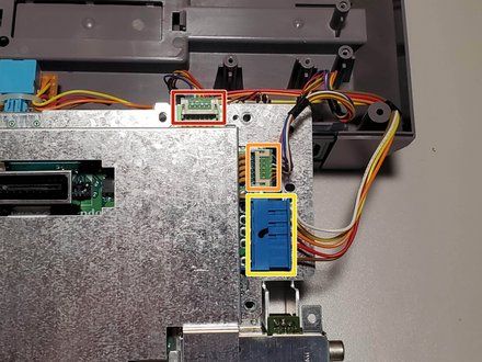
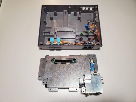
• Disconnect the wired connections from the motherboard.
• Player 1 (Shorter wires)
• Player 2 (Longer wires)
• Power/Reset Buttons
|
|
|
| | | |
| | 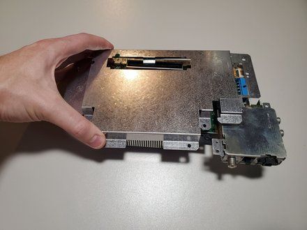
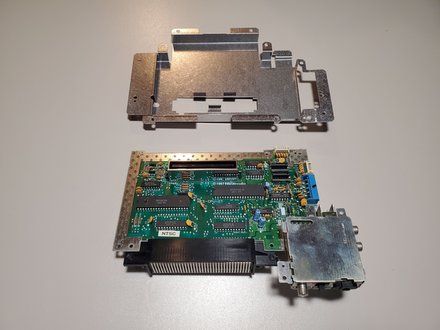
• The bottom RF shield is held on by tension around the expansion port. Lift the shield up and away from the motherboard.
|
|
|
| | | |
| | 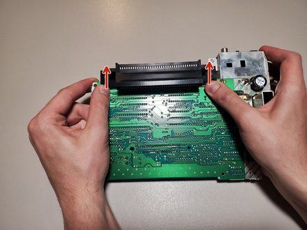
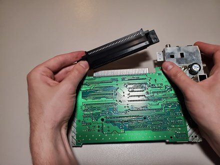
• To remove the 72-Pin connector, apply force to each edge and slide the connector off the contacts on the motherboard.
|
|
|
| | | |
| | 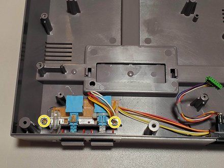
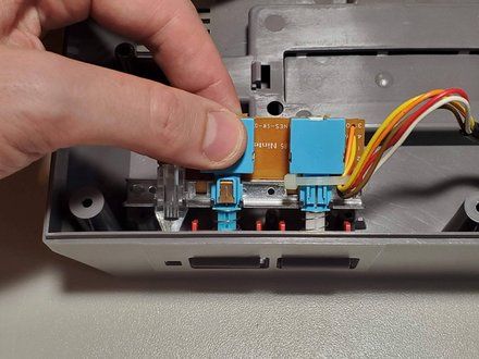
• Remove two 13.25mm Phillips screws from the button assembly. Lift slightly in the back and then up and away from the housing to remove.
|
|
|
| | | |
| | 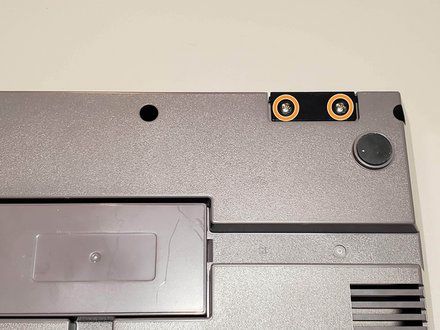
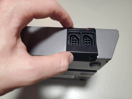
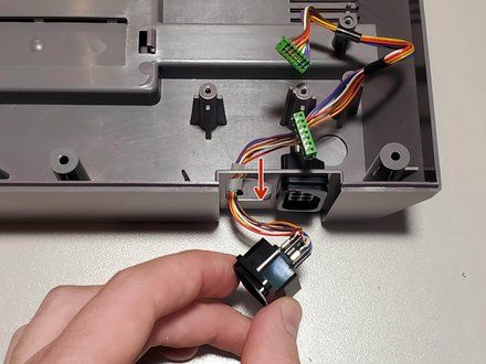
• Remove two 7.25mm Phillips screws from the bottom of the system. Lift the controller port faceplate up and away.
• Remove the controller ports by feeding them through the port holes to the front of the housing.
• REMINDER: When reassembling, Player 1 (Left) has shorter wires that Player 2 (Right).
|
|
|
| | | |
| | 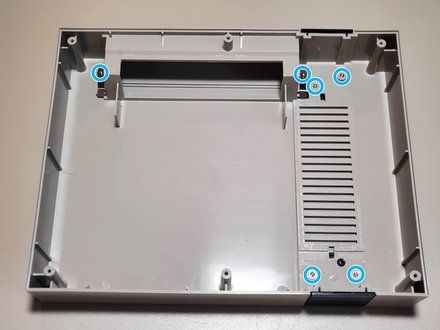
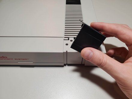
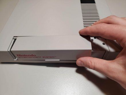
• Remove seven 7.25mm small flathead screws from the inside of the top housing.
• Two of these screws also hold a spring for the door. When reassembling, refer to the keyed shape of the plastic to orient these correctly.
|
|
|
| | | |
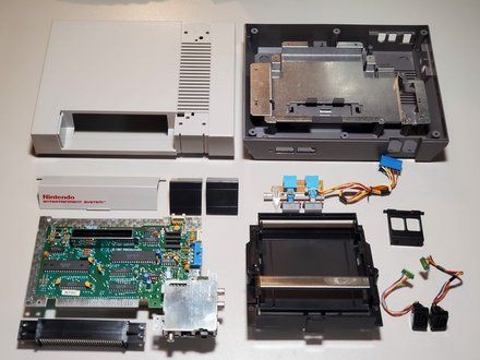
| | 
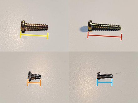
• Screw List
• (19x) 13.25mm Phillips
• (2x) 17.25mm Phillips
• (2x) 7.25mm Phillips (Silver, large cap)
• (7x) 7.25mm Flathead (Silver, small)
|
|
|
| | | |
| | | To reassemble your device, follow these instructions in reverse order. |
|
|
| | | |
|






























