|  | | Accounts are free. Join #retro on irc.fxnet.org, identify with NickServ and type !req. |
| |
|
|  | | |
| | #retro on irc.fxnet.org
6697 ssl · 6667 plain
modern + vintage clients welcome |
| |
|
| | | |
| | 3 people in #retro
okawari, synmuffin, thelounge76
nobody on the FTP
last upload: Archived Windows 3.0 - 11 ISO B... by archiveorg, 35d ago |
| as of 21:42 EST ·  |
|
|
| | | |
| | | releases | 2,186 | | last 24h | +0 | | online | 1.7 TB | | library | 1.4 TB | | members | 1 | | updated | 2026-11-18 21:42 |
|
|
|
| | | |
| |
| | 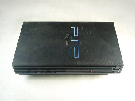
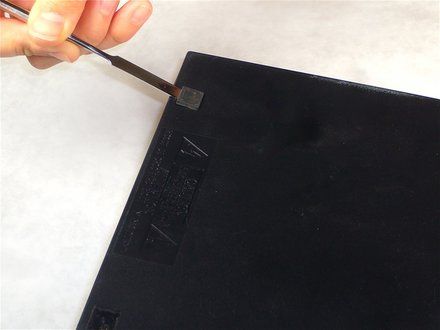
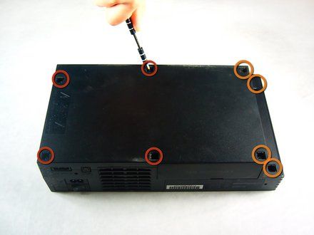
• REMINDER: Flip the PlayStation 2 over so it lays with the bottom of the device facing upwards.
• Use the flat edge of a metal spudger to pry the eight flat screw covers out.
• Remove the following eight screws securing the top cover to the bottom case:
• Four 55.4 mm Philips screws
• Four 18.0 mm Phillips screws
|
|
|
| | | |
| | 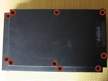
• Some models have a different number of screws and feet. Remove all the feet and screws in the bottom of the case.
• The 10 screw model has 6 screws in the bottom-most portion and 4 in the upper tray.
|
|
|
| | | |
| | 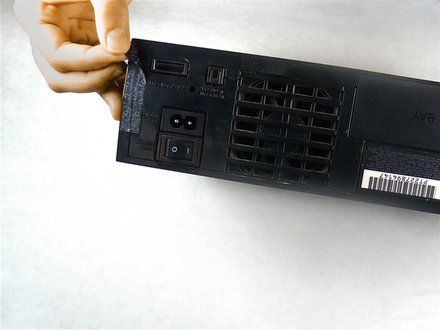
• Peel the warranty sticker (located next to the main power switch) straight away from the case.
• NOTE: To avoid activating the VOID that may come up, heat it carefully to remove and replace it clean
|
|
|
| | | |
| | 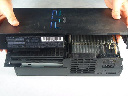
• REMINDER: Flip the PlayStation 2 back to its original upside position.
• Lift the top cover off the bottom case.
• NOTE: To facilitate the removal, it is recommended to pry open the half closer to the power switch first while rocking the top cover towards the front of the bottom case.
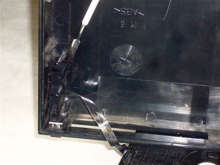
• Carefully remove the power cord that attaches the top and bottom halves by disconnecting the power cord assembly from the top case.
|
|
|
| | | |
| | 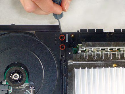
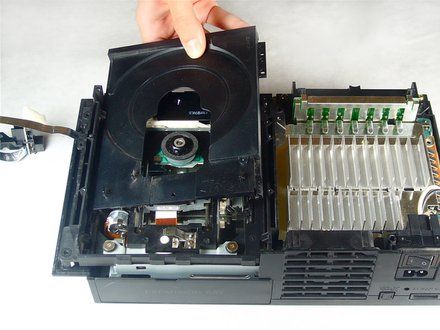
• Remove the two 6.4 mm black Phillips screws securing the optical disc drive to the bottom case.
• Lift and remove the optical disc drive straight up out of the bottom case.
|
|
|
| | | |
| | 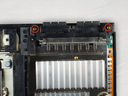
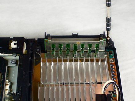
• Remove the two 14.6 mm gold-headed Phillips securing the controller ports to the bottom case.
|
|
|
| | | |
| | 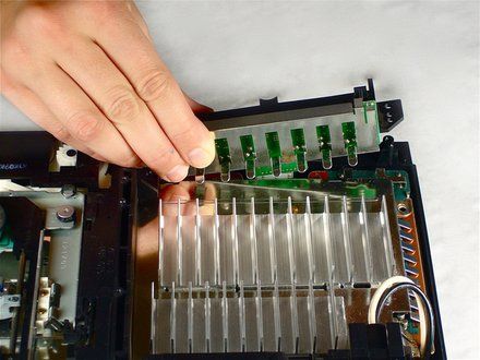
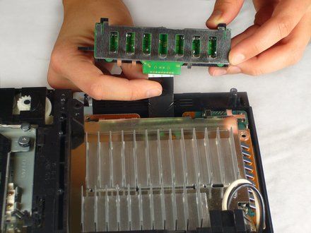
• Gently lift the controller port board out of its recess within the bottom case.
• CAUTION: Do not completely remove the controller port board. It is still attached via a ribbon cable.
• Pull the controller port ribbon cable straight away from its socket on the controller port board.
• Remove the controller port board out of the bottom case.
|
|
|
| | | |
| | 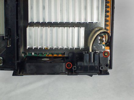
• Remove the two 14.6 mm gold Phillips screws securing the fan to the bottom case.
|
|
|
| | | |
| | 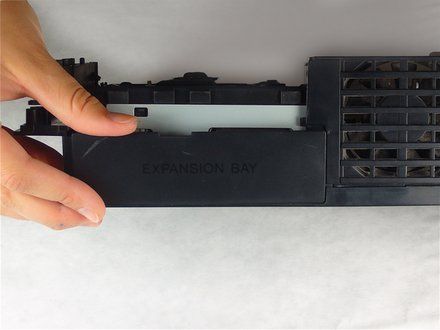
• CAUTION: If there is a device occupying the expansion bay, make sure to remove the device. The expansion base should be empty.
• Pry and remove the expansion bay cover away from its posts on the bottom case.
|
|
|
| | | |
| | 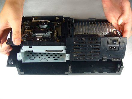
• Lift the motherboard assembly from its front edge and remove it from the lower case.
|
|
|
| | | |
| | 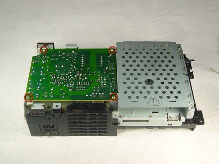
• NOTE: Now that all of that bulky plastic is out of the way, we can get to the fun stuff - electronics!
• Remove the four 7.6 mm gold-head Phillips securing the power supply to the motherboard assembly.
|
|
|
| | | |
| | 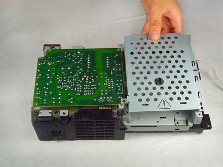
• Lift the expansion bay cage up off the motherboard assembly.
|
|
|
| | | |
| | 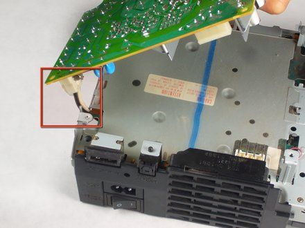
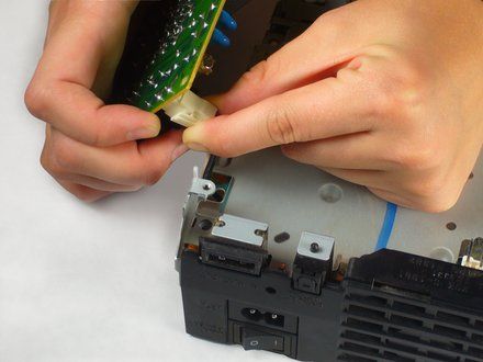
• CAUTION: Do not remove the power board yet. It is still attached to the motherboard assembly via the power board connector (highlighted in the first picture), which is located next to the main power switch.
• NOTE: Carefully lift the power board. You should now see the power board connector attached to the power board.
• Pull the power board connector straight to lift it out of its socket on the power board.
|
|
|
| | | |
| | | To reassemble your device, follow these instructions in reverse order. |
|
|
| | | |
|

















