|  | | Accounts are free. Join #retro on irc.fxnet.org, identify with NickServ and type !req. |
| |
|
|  | | |
| | #retro on irc.fxnet.org
6697 ssl · 6667 plain
modern + vintage clients welcome |
| |
|
| | | |
| | 3 people in #retro
okawari, synmuffin, thelounge76
nobody on the FTP
last upload: Archived Windows 3.0 - 11 ISO B... by archiveorg, 35d ago |
| as of 21:42 EST ·  |
|
|
| | | |
| | | releases | 2,186 | | last 24h | +0 | | online | 1.7 TB | | library | 1.4 TB | | members | 1 | | updated | 2026-11-18 21:42 |
|
|
|
| | | |
| | | |
| Device | Acer AL1717 |
| Difficulty | Moderate |
| Time | 1 hour |
| Steps | 11 |
This guide is by Deryk Lister on iFixit and is licensed under Creative Commons Attribution-NonCommercial-ShareAlike 3.0. ByteRot mirrors it for non-commercial preservation: formatting changed and photos resized for old browsers; full-size photos and the text are on the FTP in /DOCS/REPAIR. Original guide >>
Symptoms: Monitor only shows a white screen until you do several power cycles. When you do get an image it flickers heavily until it 'warms up'.
Cause: 2 failing electrolytic capacitors on the PSU board. These two are a very common failure point on this model and will be seen visibly bulging once disassembled.
This is our first guide so please be gentle. We have found iFixit repair guides useful so thought we should try and give back a little.
Tools: Phillips #2 Screwdriver; 6-in-1 Screwdriver; Pocket knife; 5mm Nut Driver; Soldering Iron; Desoldering Pump; Cutting Plier
Parts: Lead-Free Solder; 1000uF 25V Capacitor |
|
|
| | | |
| | 
• CAUTION: Before anything else, unplug the monitor! Leave it for 24 hours for the capacitors to discharge. Never disassemble the monitor with the mains plugged in.
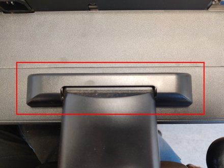
• Squeeze a little to release the clip that holds the cover in place (top middle) and lift directly away from the monitor.
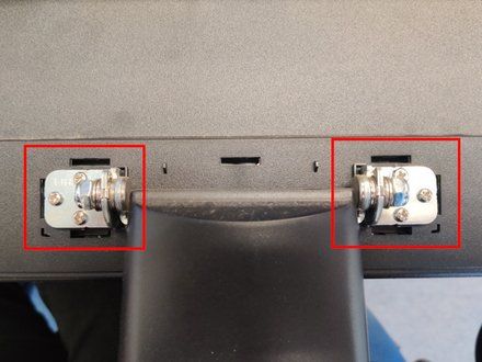
• Remove 6 Philips screws and the stand will lift straight off
|
|
|
| | | |
| | 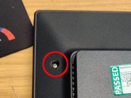
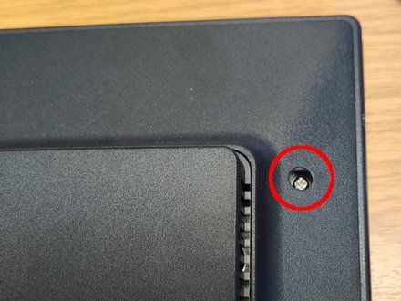
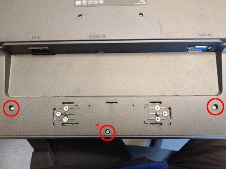
• Remove 4 Philips screws plus 1 coarse thread Philips screw (marked with *)
|
|
|
| | | |
| | 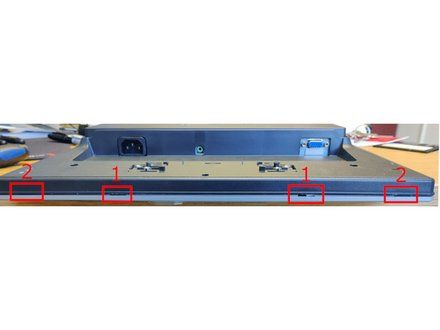
• CAUTION: This WILL break the clips (if you know a better way to release them, please let us know)
• Insert large flat blade screwdriver starting at points marked 1 and twist/pry to undo clips.
• Then release the clips at points marked 2.
• Then work your way up both sides. The cover should then (perhaps with a bit of help near the power connector) rotate and lift up from the bottom and unclip itself from the top, and come off.
|
|
|
| | | |
| | 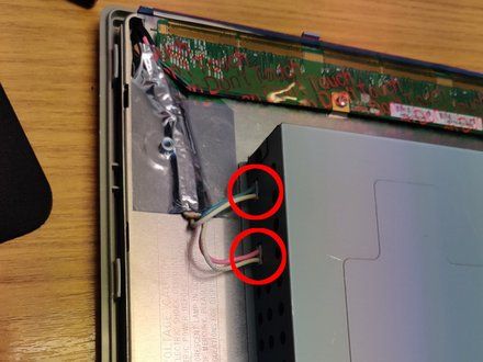
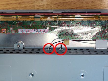
• Pull out the two plugs on the side of the inner shielding, they should pull straight out fairly easy. Note blue at top and pink at bottom.
• Do the same for the two plugs at the top.
|
|
|
| | | |
| | 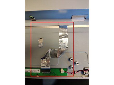
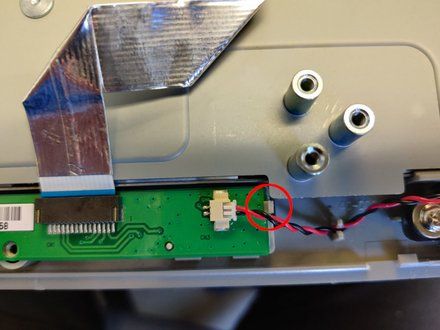
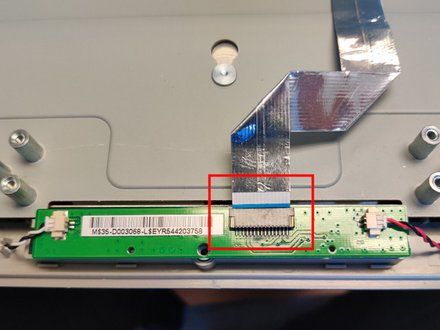
• Gently peel this ribbon cable off the shielding.
• CAUTION: These ribbon cables can be fragile so do not excessively bend, stretch, twist etc - it may help to slide a credit card underneath to loosen the adhesive.
• Pull the plastic retaining clip away from the PCB (gently so it doesn't break) to remove the PCB for better access to the ribbon cable connector. It'll still be attached to the speakers but we are only loosening it.
• Pull ribbon cable carefully out of its connector.
|
|
|
| | | |
| | 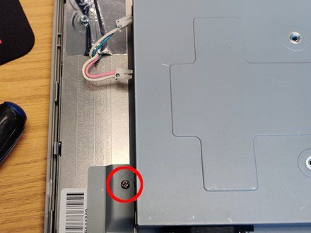
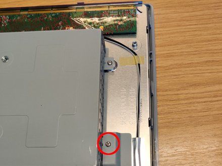
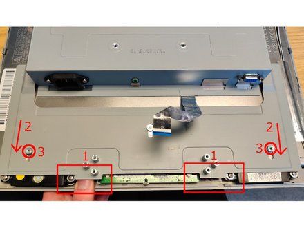
• Remove 2x Philips screws bottom left and bottom right of inner shielding to release the sliding plate
• The plastic surround at points marked (1) can be pushed outwards a little (away from and perpendicular to the LCD panel) e.g. with a thumb and forefingers as shown, which gives clearance to the metal plate so it can slide in the direction of the arrows (2) until the slot is aligned as in (3). This plate can then lift off.
|
|
|
| | | |
| | 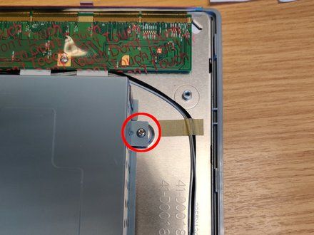
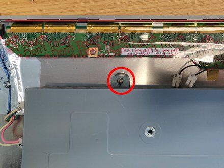
• Remove 2 remaining Philips screws from top left and top right of inner shield
|
|
|
| | | |
| | 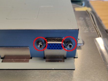
• Use 5mm hex socket or plyers to undo the VGA retaining hex nuts
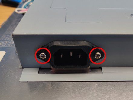
• Remove 2 Philips screws from AC connector
• Then the inner metal shield/housing can finally be lifted off (directly upwards) to expose the circuitry.
|
|
|
| | | |
| | 
• CAUTION: Capacitors store a charge, which can shock you. The ones on this board are relatively small and should be harmless, but to be on the safe side leave it unplugged for 24 hours and consider using a capacitor discharge probe or multimeter set to current measurement to discharge them.
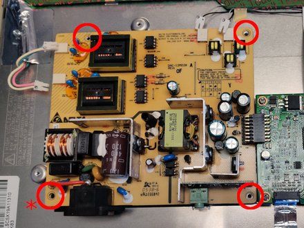
• Remove 3 Short Philips screws and 1 large Philips screw with washer (marked *) to release the PSU board. It pulls upwards a little off the standoffs and directly away from the connector to the logic/i/o board.
|
|
|
| | | |
| | 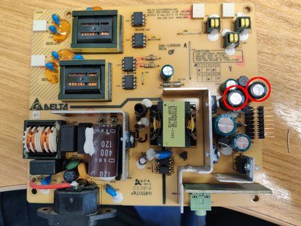
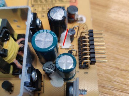
• Identify the two capacitors to be changed as circled. Make a mental note of their orientation in case you happen to have a different version of the board, or take a photo. It is likely that they are bulging at the top, and possibly leaking. (Not visible in the first photo as it was taken with the new capacitors in place)
• Use the pocket knife to slice along the line shown in the second image to free the capacitor from the 'glue' that is sticking it to other components and do the same for the glue on the other capacitor. The image shows one of the bad capacitors removed and the remaining bad one (you can see the bulge here)
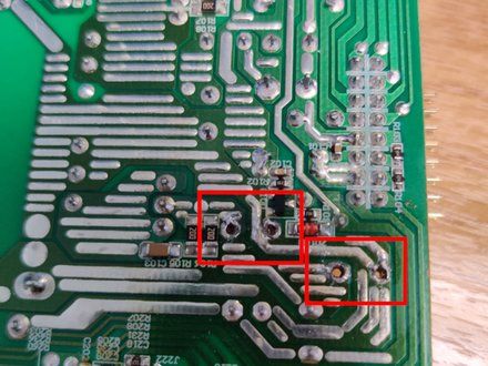
• With the aid of a solder sucker (https://www.ifixit.com/en-ca/products/desoldering-pump) or desoldering braid, desolder the capacitors - their location from the circuit side is highlighted in the third image (which shows both removed). You will need to pull on the capacitor from the component side of the board while heating each leg alternately, 'walking' it out of the board.
• Ensure the holes are clear of solder so that the replacements will go in.
|
|
|
| | | |
| | 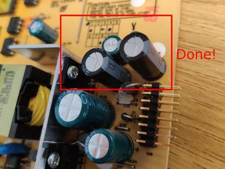
• Solder in the replacement capacitors, making sure to get them the right way round as identified in step 10 (negative will normally be a stripe on the capacitor, and on this particular board both face the nearest edge). The PCB on the component side also shows which side is positive.
• CAUTION: Take care not to create any solder bridges.
• Use the wire cutters to snip the excess lead once they are soldered in place.
• You're done! Now you can reassemble and test the monitor.
|
|
|
| | | |
| | | To reassemble your device, follow these instructions in reverse order. Take care when pushing the ribbon cable back into the connector from step 5. |
|
|
| | | |
|




























